At Last!. I have started on my car ;-)

Status
Not open for further replies.
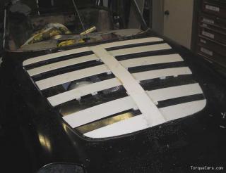
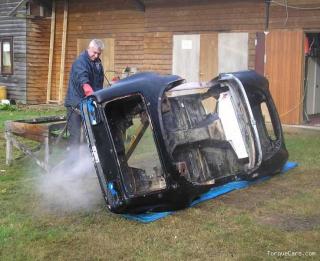
For anyone interested, here is a photo of my car. As can be seen, a little more work is required to get it road legal :) But at least I have started.

Welllllll, there would be a picture here (less than 97kb as requested) if only the system would let me post it. It keeps saying that I have exceeded my quota by 67Kb! Help please Waynne
 
you must be spending HUGE amounts on that car.
the question is, will you be putting a body kit on it?

i bet you've even gone as far as to change the wheel nuts to light weight titanium or similar ones heh.

There isn't a body kit for the Elan. Mind you, I wouldn't fit one if there was!

As you will see in the list, splitter, underfloor smoothing and diffuser are proposed.

Yes, titanium wheel nuts will be used :) Aluminium nuts and bolts are also being used where appropriate.
 
thats a big list.

going to be a very impressive machine when finished.

i didnt mean like,,, a bolt on body kit, i ment the kind what are custom made for better air flow resistance and and downforce, the kind that dont look that different to standrd ones. just with a few wings and holes.

but as you'r going to put diffusers and splitters an stuff on you need'nt worry lol...

i would love to be in the passangers seat on the strip to feel the immense G forces.
 
Last edited:
A bit of back road fun perhaps ?

Perish the thought :)

Actually, that is what the Robin Hood is for. The Elan will be just too quick for that and I would probably end up killing myself (too much power, not enough skill).
 
Photos showing progress on re-shaping bonnet, This is required in order for bonnet to clear cam pulleys and for a new scoop to allow air out of engine bay so that the radiator and intercooler work properly. Once shape is finalised and covered with fibreglass I will look at the scoop design. Doesn't look a lot different to the original, which was the idea. Middle of bonnet is approx 25mm higher.

When the scoop has been designed and added I will send it off to my tame carbon fibre guru for it to be made in CF. Original bonnet weighed 8.5Kg. CF one should be around 2Kg.


Last edited:
Thats a nice and subtle bulge. Why not put a vent in the back to keep temps down in the engine bay?

Thanks, took me all day.

Vents at the back of bonnet don't work very well as this is a high pressure area. Vents need to be in low pressure areas so the air can get out. This is usually approx 1/3 up the bonnet. The plan is to put a vent just in front of engine. However, I spent all Sunday designing and fabricating a scoop pattern only not to like it once finished! Re-looking at problem as aesthetics in this area are very important, any scoop has to look like is was always part of the car and not just a boy racer add-on :)
 
um,, right now i may be wrong. but heres what i think would work in regards to scoops.

as you have got a nice size apeture in the front for air to come in for the intercooler, that air will also go into the engine bay.

so if you were to put a rear facing scoop near the back of the bonnet the air that is coming in via the intercooler hole will be exiting out the rear facing scoop so it just flows in and out?

im no enginer but i would think that that would work?

now correct me heh
 
no i think the air going over the bonnet is at a higher pressure that the air that is trying to get out from underneath ( this air can go under the car at a lower pressure area )
the higher pressure will effectively seal over the scoop little air will come out.
Of course it wll make a difference if the car is stationary and cooling fans are on
 
The front of my car is very wing shaped, ie flat bottom and convex top. therfore the air flowing over the bonnet has further to flow than the air going underneath and so has to speed up. This speeding up of the air reduces the pressure. So, if the scoop is placed towards the front of the bonnet (in the area between the radiators and front of engine), the pressure differential between the air flowing over the bonnet and that trapped in the engine bay will cause the air to be sucked out of the engine bay (hopefuly).

The air pressure near the base of the windscreen is a lot higher so any scoop located here will be far less efficient, due to the smaller difference in pressures and the fact that the under bonnet air will have a hard time getting to the scoop past the engine, turbo, plenuum, etc.
 
Last edited:
ah i think i understand.

so is the idea of a read facing scoop good or bad? (where it is located i dont know, the best place for the pressure malarky)
 
um,, right now i may be wrong. but heres what i think would work in regards to scoops.
as you have got a nice size apeture in the front for air to come in for the intercooler, that air will also go into the engine bay.
so if you were to put a rear facing scoop near the back of the bonnet the air that is coming in via the intercooler hole will be exiting out the rear facing scoop so it just flows in and out?
im no enginer but i would think that that would work?
now correct me heh

Oh, if was only that easy :) Air flows from high to low pressure. Although the air in the engine bay will usually be in a high pressure state (slow moving), the air pressure near the back of the bonnet is also high so the flow effeciency will be low. You need to find an exit in a low pressure area in order to gain as much pressure differential as possible.

One option I am looking at is exiting the air into the wheel arches, as these are often low pressure areas due the the action of the rotating tyres. I could then put slots into the wings (where the pressure over them, due to their convex shape, is even lower) thereby increasing the flow still further.

In the end, as I don't have a wind tunnel, it will be trial and error and a lot of road testing using short pieces of wool taped to the car :)
 
ah i think i understand.

so is the idea of a rear facing scoop good or bad? (where it is located i dont know, the best place for the pressure malarky)

Depends entirely on what you are trying to achieve. Rear facing to get air out (placed in low pressure area), front facing to get air in (located in high pressure area).
 
well if you have the front opening, where the intercooler will be behind, air goes in.

then you have a read facing scoop, air goes out?

if you found an wind tunnel would you use it? and would that cost the earth to be able to use one?

also if you exit the air into the wheel arches wouldnt you need some sort of deflectors to get the air out of the arch as it would cause turbulance and corse some sort of problems with airflow round the side of the car?

i would have thought that upwards would be the best way because then, i know it would be next to nothing, but it act like downforce whereas if you deflected it down or sideways it could act like lift??

Air will ONLY come out if there is a pressure differential. The bigger the differential the more efficient the system.

MIRA hire out their tunnel for around, I believe, 5000gbp a day (plus technicians).

One technique is to channel the air around the front of the wheel into another low presure area.

Didn't say it was easy, or that I know all of the answers :)
 
um....wow, thats a lot to hire one for a day.

have you got a lot of the pressure and airspeeds/lift variables sorted??

i might be able to get you in touch with someone through a garage i know to do with airodinamics(i know its spelt wrong), will ring them up tomoro about it if ya want.

they might be able to help you with the deflecting for the least amount of turblance and negative effects of deflecting to an inefficiant area among other things.
 
Latest update.

Photos show body being pressure cleaned prior to being paint stripped ready for repairs and mods.

P.S. This isn't me, by the way :). A friend has come over for the week to work on the car.


Last edited:
um....wow, thats a lot to hire one for a day.

have you got a lot of the pressure and airspeeds/lift variables sorted??

i might be able to get you in touch with someone through a garage i know to do with airodinamics(i know its spelt wrong), will ring them up tomoro about it if ya want.

they might be able to help you with the deflecting for the least amount of turblance and negative effects of deflecting to an inefficiant area among other things.

Sounds interesting, Where are they?
 
i have to get hold of my cousin, there in aylsford. its been a bit hard getting hold of them atm, but will keep trying, if not i will ask around for you. so how long do you think till its finished?? and will you be at the TC meet?
 
i have to get hold of my cousin, there in aylsford. its been a bit hard getting hold of them atm, but will keep trying, if not i will ask around for you. so how long do you think till its finished?? and will you be at the TC meet?

TC meet, when is that?
 
sometime in november i think, we are still discusing the details in the meets section.

and i spoke to my couz, and he said basically it would be wind tunnelage, and costly :/

im sure some good tuning place around will help you or point in the right direction.
 
sometime in november i think, we are still discusing the details in the meets section.

and i spoke to my couz, and he said basically it would be wind tunnelage, and costly :/

im sure some good tuning place around will help you or point in the right direction.


November? This year? Take another look at the photos :)

Hope to have it working by March 2009

Wind tunnel hire at MIRA is approx £5000/day

I already have a couple of good race car and engine builders on my side, so I won't starve for help :)

Thanks for trying, anyway.
 
aah yeh, i see what you mean lol, well you could wrap up well lol.

or take......um..... your landy?
 
Latest update

Along with the front grill/splitter as discussed in the styling thread, the bonnet has progressed. As the new engine is taller than the original, the bonnet had to be modified. As I also needed to improve the airflow out of the engine bay, I took the opportunity to get a carbon fibre one made.

Last weekend Nick came up from Southampton with the 'rough casting' to check for fit (a bit like having a saville Row suit fitted). Fortunately, it just clears the engine :)

Lots of trimming and clear coating to be done. Original weighed 8.5kg, this will end up under 2kg :)

He left with the bonnet and both original doors :)

 
Last edited:
Been scanning this thread and I am impressed with the work carried out, the Cosworth lump alone does it for me :D Looking forward to seeing more of this and when it is finished.
 
was the original one fiberglass as well ?
didnt relise the carbon would be that much lighter than f/glass

Yes, whole body is FG. The bonnet had a steel tube around the front section for stiffening and bonnet spring securing.

The boot weighed 6Kg in FG and is now just over 1Kg in CF.

Door shells should end up around 2Kg each instead of the original 6Kg ( needs to be stiffer than boot so less saving).

Body shell weighs just over 96Kg and is estimated to end up around 20Kg in CF. In total I hope to save around 95-100Kg using CF. This equates to approx 15% saving on the total car's weight, bringing it down to around 550Kg.

The lightness comes from the fact that CF mat is far stronger in its natural state so you need far less CF mat to get the same strength when compared with FG. Add another layer and it is much stronger than CF and still far lighter.
 
Last edited:
Been scanning this thread and I am impressed with the work carried out, the Cosworth lump alone does it for me :D Looking forward to seeing more of this and when it is finished.

Much appreciated, especially coming from a serious racer.

Your thoughts (or anyone else's for that matter) would be most welcome on my present dilemma. The car has unequal length adjustable wishbones at each end. With the bottom wishbones parallel to the ground the car has just over 6 inches of ground clearance (standard ride height for the Elan). I would like to achieve 4-41/2 inches, but this would put the outer bottom wishbone pivots lower than the inner ones - not good practice.

My question is, would lowering the C of G by 2 inches compensate for the bottom wishbones being at the wrong angle? I should be able to adjust out most if not all bump steer and the suspension travel is very limited.
 
Last edited:
Easy, I wouldn't say I was a serious racer, but enthusiastic!

Do you have a drawing or decent photo of the current set-up? Like you said, you need to ensure you maintain the suspension travel and bump-stop zone. 2-2.5" is alot to drop on an OE set-up. Normally race cars would have the replacement suspension re-mounted to ensure the geometry is not upset. Lowering by that amount can create a multitude of issues if not carried out right and the car will not handle at all, if anything it will drive itself around lines you don't want it to.

When trying to drop 2" you get into anti-roll bar issues, so these will need looking at as well. A bit hard without seeing the set-up, but I may be barking up the wrong tree.

I realise that a 2" drop is unrealistic without huge chassis mods (not prepared to do) or a change to a spaceframe (not yet).

However 6" is a tad high for such a small car. If I could achieve 5" with exisiting suspension mounts I will be happy with that for now.

Original front anti-roll bar connected to the bottom of old dampers and wasn't adjustable. New set-up precludes this so a new one has yet to be designed and installed. The rear will also have an adjustable bar (not fitted on Elan originally).

I appreciate that lowering a car can create a lot of problems - I have written about this previously on this very forum :).

Top wishbones are adjustable on both front and rear set-ups.


Last edited:
That will be hard to achieve a 2" drop without upsetting the geometry. The ideal way to lose that much height is to reposition the suspension to ensure the moving geometry is kept within its designed parameters.

I'll have a think on this after looking at those pictures.
 
i have just read through all of this took me like 20 mins haha this car is going to be amasing it looks lovely on the flatbed, i like the rims 16's may be more practicle but 17s look good keep up the good work and get a vid of your first run lol !!!
 
i have just read through all of this took me like 20 mins haha this car is going to be amasing it looks lovely on the flatbed, i like the rims 16's may be more practicle but 17s look good keep up the good work and get a vid of your first run lol !!!

Thanks.

17s will probably be fitted to rear (as in photo) but the front will be 16s. This will give the car a slight rake thereby helping underbody downforce generation and also reduce the front unsprung weight.

However, the rims were borrowed from my son just to keep the corners off the ground! They show too much of the suspension for my liking so the car will be shod with a modern version of the old style slot mags (with more but narrower slots) made by Superlite (not listed on their site but available to special order)
 
Status
Not open for further replies.
Similar threads
Thread starter Title Forum Replies Date
swompy Started modding my Corrado Projects & WIPs 12

Similar threads


Please watch this on my YouTube channel & Subscribe.


Back
Top