my daily/party bus/camper/toy box

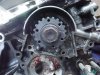
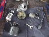
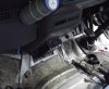
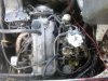
ok people this is my first ground up build i have a 91 ford econovan/mazda b2000 got off a mate
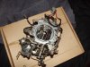
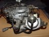
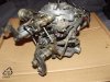
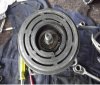
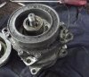
it has petol and gas fitted, engine is a 2.0L carby fed FE that will become a force fet FE/T with a little toyota ct9, i already had this and being off a 1.8L it should boost eary for towing power and i'll keep it set around 5-7lb of boost

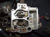
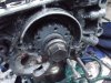
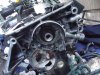
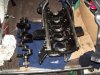
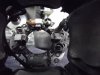
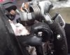
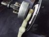
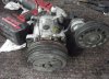
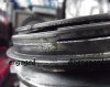
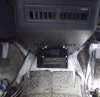
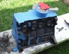
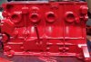
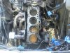
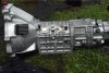
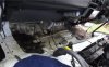
i have left the block bolted in the van i'm too lazy to pull it out plus i'm covered when it rains, i have removed the pistons so she's ready for a hone
all rings and bearings will remain standard
my questions are,
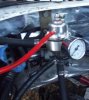
would standard rings and head gasket be ok with 5-7 pound boost, the boost controller will be mounted in the cab and plumbed to the factory internal wastegate so i have full control.

i have looked everywhere for timing settings to do with retarding and i have found nothing definate only suggestions and off topic ranting so any help there would be great,
also people who have helped/added to this build will be getting thier name on the (built with help by) section that is reserved on the tail gate after the painting is complete
 
It sounds like quite a project you have there. Sort I can't help with any of the specifics of the engine timing as I have no experience of them.
 
it's been an interesting build. i have found so far, small pits in all the piston heads but head is clean, a small spring and wire in the sump, 12 valve pistons in an 8 valve engine, material missing from the oil journal hole in the rod bearings, damaged intake valve shaft and broken guide and i'm just getting started
 

Attachments

  • Photo0284.jpg
    Photo0284.jpg
    49 KB · Views: 4
  • Photo0291.jpg
    Photo0291.jpg
    56 KB · Views: 2
  • Photo0283.jpg
    Photo0283.jpg
    27.7 KB · Views: 1
  • DSCF0241.jpg
    DSCF0241.jpg
    45.1 KB · Views: 2
Last edited:
on closer inspection i found the crank has about 1 - 2mm of north/south movement so it was a waste of time leaving the block mounted up, anyhow the original heat proofing was ugly and torn so i steamed cleaned and re-insulated all the (hood/seat) panels, now that the crank bearings need replacing i dropped the box and scraped all the grease and dirt off (HINT don't try and cheat with this, there is not enough play in the uni to drop it out, unbolt the shaft from the diff first!) and greased all the ball joints and linkages. the ratty old carpet was pulled up and all the dirt and mud that had been collected over
the 21 years was steam blasted out.
 

Attachments

  • DSCF0259.jpg
    DSCF0259.jpg
    47.5 KB · Views: 1
  • DSCF0250.jpg
    DSCF0250.jpg
    57.9 KB · Views: 3
  • DSCF0251.jpg
    DSCF0251.jpg
    40.5 KB · Views: 3
cheers boys, i hope this helps at least one person looking at doing a similar job as i'm in the deep end with this build and cant find much info on any of my mods. well i pulled my carby down for a health check tonight and i think it needs some physiotheraphy...

i still cant find any info apart from it might be a nikki, i have been annoying google for the past month and cant get any solid info. any help would be great. a quick look inside my beautiful bowl
 

Attachments

  • DSCF0261.jpg
    DSCF0261.jpg
    45.2 KB · Views: 4
  • DSCF0265.jpg
    DSCF0265.jpg
    41.4 KB · Views: 3
  • DSCF0263.jpg
    DSCF0263.jpg
    42.2 KB · Views: 0
  • DSCF0264.jpg
    DSCF0264.jpg
    44 KB · Views: 0
for people looking at pulling down a fe block to remove the crank.
you will need to remove the box, clutch and fly wheel, behind the fly there is the crank seal, unbolt and gently remove, at the other end undo the large bolt (i used a 28v rattle gun as it will be tight) and remove the timing pully but dont lose the key (little piece of steel holding the pully in position).
then unbolt and remove the oil pump and gently lift out the crank.
in the last pic i put the pully back on to keep the key in place.
 

Attachments

  • DSCF0269.jpg
    DSCF0269.jpg
    49.5 KB · Views: 0
  • DSCF0270.jpg
    DSCF0270.jpg
    48.5 KB · Views: 1
  • DSCF0271.jpg
    DSCF0271.jpg
    59.1 KB · Views: 0
  • DSCF0274.jpg
    DSCF0274.jpg
    54.4 KB · Views: 0
yet another day of white knuckle excitement, i was unsure if my starter was going to be up to the challenge of turning a fresh motor so a strip down inspection was on the books. it's the factory starter and i needed to check the brushes were in good order and they are (good enough for a few more years) so if you are thinking yours is getting lazy check it and replace the brushes if they are worn out. it pulls down easy but re-assembly is always hard if you don't know what you are doing, this is how i did it. PIC 1 all the parts, PIC 2 the brushes, PIC 3 its not very clear but i put the spinny dowacky bit armature or what ever you like to call it back inside the case, push the brushes one at a time so they slip back into the guide and gently sit the brush on the copper contacts on the end of the dowacky, do the same to all the brushes so they look like pic 3 then slip on the starter base and screw the brush plate back down.

PIC 4 the rocker arm connectes the starter with the flywheel then you turn the key so dont get this part wrong, my rocker is shaped so it only goes back in one way (the right way), i sat it in place as seen in pic 4 then chuck on the top of the starter but leave a small gap then i inserted the rocker plate and rubber (the rubber pushes the plate and keeps the rocker arm moving smoothly) then put the long bolts in and tightened them up.
 

Attachments

  • DSCF0291.jpg
    DSCF0291.jpg
    46.9 KB · Views: 2
  • DSCF0292.jpg
    DSCF0292.jpg
    34.1 KB · Views: 0
  • DSCF0293.jpg
    DSCF0293.jpg
    33.9 KB · Views: 0
  • DSCF0296.jpg
    DSCF0296.jpg
    30.7 KB · Views: 0
  • DSCF0299.jpg
    DSCF0299.jpg
    40.6 KB · Views: 0
PIC 5 the top and bottom are back together, grab the center from the solenoid and hang it on the rocker arm as in pic 5, place the spring back in as you can see in PIC 6, slip it over and bolt it up. make sure it bolts back up in the same direction it was before you removed it, PIC 7 all done, if not sure you did it right test it with your battery and thick wire. test the motor if it spins you are good, check the solenoid if it clicks and moves the gear up and down you are a legend!. if this has helped or entertained you hit the add rep button.
 

Attachments

  • DSCF0300.jpg
    DSCF0300.jpg
    42.1 KB · Views: 0
  • DSCF0301.jpg
    DSCF0301.jpg
    35 KB · Views: 0
Looks to be an interresting project mate, I do like home brew engine projects so I will be keeping my eye on this one,

Is your engine the same as the Ford Pinto we had over in the UK?
Also I'm not sure if that nikki carb is factory fit as they did a lot of retro fit kits for loads of engines "back in the day" so maybe a different one is in order because (so I've been told) Nikki's aren't very good, just make sure that your new one has been sealed for forced induction even though it's a low boost system and it's been jetted correctly, you should be looking to get the A/F ratio at around 11.5/12.5:1 so you don't melt your pistons, also on any FI application it's a good idea to use the highest octane fuel thats readily avaliable to you so you don't get pre detonation in the cylinders. As for the spark timing, you can get distrubtors that have boost retard on them so your cylinder pressure don't get too high and save your engine from predetonation,

hope this helps a bit

Also what HP and torque is the standard engine rated at? and at what rpms? What turbo are you using, make and model would be nice to know

Brett
 
as far as i know it's mazda, 2.0, fe with the 8v sohc, nikki is a real piece of.
it's too complex and we all about vs simple, i have a twin bbl webber of a straight 6cyl that was dual fuel and has auto choke so i dare say the nikki will become an ebay job or i'll just bin it.

i still need to read up on compression and a/f ratios but i'll definately keep that one in mind, the specs for these fe engines are:

The 2.0 L (1998 cc) FE has a square 86 mm bore and stroke. It was available as an 8-valve SOHC and 12-valve SOHC. Outputs are 90 hp (66 kW) for the 8-valve 1 barrel carburetor version, 80 hp (74 kW) at 4500 rpm and 110 N·m at 2500 rpm for the 2 barrel carburetor version 3., or 118 hp (88 kW) at 5300 rpm and 178 N·m at 3700 rpm with fuel injection, 12-valve SOHC and higher compression (10:1 vs 8.6:1).

and the fe/t The 2.0 L (1998 cc) fuel-injected, turbocharged FET version of the FE produced 135 hp (101 kW) at 5250 rpm and 175 ft·lbf (237 N·m) at 2800 rpm. It was a variant of the 8-valve SOHC FE Featuring a small turbocharger and no intercooler producing 7 psi of boost. As such it features the same 86 mm bore and stroke of the FE. The Japanese variant of this engine was dubbed the Magnum Turbo. Given that the peak power for the naturally aspirated, fuel-injected FE is 118 hp (88 kW), the rated power for the FET is said to be conservative.

i'm still looking for timing specs for the fet as i'll be boosting to 5-7lb max and it's basically what i'm building. the turbo is a toyota CT9 with an internal wastegate, i need it will spool early so i can get my van, jetski and off-road buggy (it just fits in the back) up maquarie pass and up the clyde as it's a really steep 25 minute trip to the top, the van is a 91 st ford econovan maxi and it's an ex-delivery van so she needs some love'n after all the abuse she recieved.
 
i noticed the a/c pump was making a squeaking noise when i turned it on plus i knew it was low on gas so i will be having look, i had a bloke come out and de-gas the system which was easy because it was completely empty.

first grab your rattle gun and remove the center nut, i scewed 3 bolts from my tapper cover into the the threaded holes to lift off the cluth plate seen in pic 1, tighten them evenly or it will bend the clutch and strip the threads, next remove the two retaining clips (inside pic 2) and the pully has to come off and these were TIGHT so i used a huge screw driver handle (thick rubber handle) and repeatedly hit one side of the pully then the other while lifting it with my other hand.

once removed clean all the gunk off the electro magnet (big round thing on the top of the pump in pic 3) and be careful not to damage it, if the bumpy looking resin on the magnet has cracks in it you will need to get it replaced, once cleaned re-assemble it and test the electro magnet. doing this is easy as, hook up the negative from your battery to the pump housing and grab the wire on the top of the pump in in pic 4 and tap it on the active, you should hear the clutch slam shut dont touch the clutch when you do this. the clutch should move the same as pic 5.
 

Attachments

  • DSCF0303.jpg
    DSCF0303.jpg
    47.5 KB · Views: 0
  • DSCF0305.jpg
    DSCF0305.jpg
    44.5 KB · Views: 0
  • DSCF0306.jpg
    DSCF0306.jpg
    43.5 KB · Views: 0
  • DSCF0302.jpg
    DSCF0302.jpg
    55.7 KB · Views: 1
  • DSCF0307.jpg
    DSCF0307.jpg
    39.5 KB · Views: 2
after a few days of phone calls and research i've decided how i'm going to combat my future detonation problems, i'm going to leave the dizzy stock and install a standalone individual cylinder knock control ignition system and piggy back it with a spark boosting ignition system(all plug and play). then i just dial it in on the road or on a dyno. well it's almost that easy.
 
finally contacted the company that made my cruise control unit, it runs off vac pressure which will become a problem when the turbo creates boost so customer service suggested i use 3-4 vac tanks, buy a (restricted purchase! not really sure how that is supposed to work) solanoid unit for $300, or build a custom tank and use the original valve. so custom it will have to be.

i am sick of looking at the sun damaged steering column plastics so i got my trusty sanding block and went to town, it made a huge diff but now i'm thinking of either painting the plastics or carbon fiber wrap. the block is all masked up, got a can of hot rod red engne enamel off ebay for $14 , still deciding if i should paint the gearbox, head and tapper cover aswell and what colour they should be.
 

Attachments

  • DSCF0367.jpg
    DSCF0367.jpg
    42 KB · Views: 0
  • DSCF0366.jpg
    DSCF0366.jpg
    33.3 KB · Views: 0
  • DSCF0365.jpg
    DSCF0365.jpg
    32.8 KB · Views: 1
  • DSCF0370.jpg
    DSCF0370.jpg
    60 KB · Views: 0
build is going slow until my hand is fixed but my 6yr old nephew is helping out where he can, my rising rate fuel pressure reg is in, block has a fresh coat of red paint coz it makes it faster and mt new acl duralite .50 o/s pistons that i got off ebay for $4. YES 4 BUCKS!, i had engineer approval for my side exhaust but there is a catch the fee for the certificate is quoted at $600.00-$800.00:amazed:
 

Attachments

  • DSCF0385.jpg
    DSCF0385.jpg
    30.5 KB · Views: 0
  • DSCF0380.jpg
    DSCF0380.jpg
    46.7 KB · Views: 0
  • DSCF0381.jpg
    DSCF0381.jpg
    32.1 KB · Views: 0
  • DSCF0382.jpg
    DSCF0382.jpg
    23.3 KB · Views: 1

Similar threads


Please watch this on my YouTube channel & Subscribe.


Back
Top