
You are using an out of date browser. It may not display this or other websites correctly.
You should upgrade or use an alternative browser.
You should upgrade or use an alternative browser.
At Last!. I have started on my car ;-) PART 2
- Thread starter pgarner
- Start date


Teenager2413
Torque Junkie
 i read this entire thread tonight (night shifts suck at a hmp) but cor blimery OG you have sooem amazing work here would love to see this at some point make the work my dad and i are doing at them moment look pathetic , we are building a lotus super 7 from scratch but your is incredable
Teenager2413
Torque Junkie
Thanks, it has been a long haul with many design changes along the way.
Building a kit car from stratch is no mean feat. Which version are you building? Using a preformed chassis or really starting from scratch?")
hello OG are starting from complete scratch making the chasis by hand the chasis is complete with ether side with in 3 mm of each juts at them moment me and my dad are working alot and funds are abit tight as the enginge need a rebore etc lol
the version were building i think is a locust 7 my dad had some orignal plans from donkey years ago we used a sierra running gear but we sourced a 2l pinto for it as the car i got we relised had a pathetic 1.8 pinto in it
Teenager2413
Torque Junkie
okay i will it has been slow lately as i said but we have kept detailed photos from the of for the sva test because we have kept the orignal car parts were hopeing to get the right reg not a q platewhat carbs are you using on you robin hood engine ?


Teo
Road Burner
Thanks, it has been a long haul with many design changes along the way.
Building a kit car from stratch is no mean feat. Which version are you building? Using a preformed chassis or really starting from scratch?
If our passion was not a MAJOR factor in our obsession? Then these rides could cause a SANE man to go over the edge very easily! Hey Old-Git, Job Well Done!!!!!! 

A classic example of how taking the easy route often ends up the hardest route.
I was routing the fuel pipes through the chassis and had to get them past the hole where the prop passes through to the diff. The flange was difficult to get to to drill so I decided to run the pipes through the opening. This seemed to work:
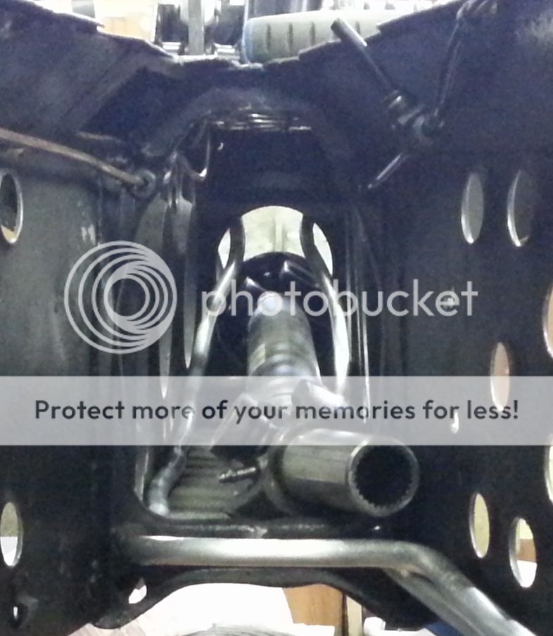
Next job was to clamp the pipes to the chassis. I was going to make the pipe clamps out of scrap aluminium but, at under £4 each, I decided it wasn't worth the time and effort. These arrived today so I set about clamping the pipe. This is the fuel return pipe:

The prop was making fitting the clamps awkward so I tried to remove it only to discover that the fuel pipes prevented the prop flange passing though the access hole!
So I am now in the process of drilling the awkward holes (drill and file as my 90 degree drill adaptor only takes up to 10mm drill bits and I need 13mm holes). Finished one side and will complete the other tomorrow. In the above photo there is a brake pipe clip under the fuel pipe which I will re-site tomorrow.
T9 man
TC ModFather
Have you not got a cone cutter Steve? They usually have a 10 mm diameter shaft but go up in size stages. This way you could still use the right angled drill adapter. They do step versions too so once you have drilled the right size hole, it is harder to make the hole bigger by accident unless you apply pressure.
T9 man
TC ModFather
Hall make some different ones for heavy gauge metal as well as stainless steel by all accounts. I'll ask my wholesaler for a couple of part numbers for you. In the meantime, step up to three shredded wheat
Thanks Os, but I have cracked it!
Remembered that I used hole punches on the chassis and that I had smaller ones. Dug these out and they worked, although it was trickly aligning them as the pilot hole was too big.

http:
//i294.photobucket.com/albums/mm94/elanses3/fuelpipes1611145_zpsf778bca8.jpg
Pipes clamped to chassis:

Pipes through chassis ;


Flow and return pipes with bulkhead fittings losely in place;

T9 man
TC ModFather
Started to assemble nearside rear suspension today. The carbon fibre push rods will be painted silver so any stresses will be quickly visible. Besides, I don't want any carbon fibre to be visible

Also started looking at how to fit the roll cage. This plate sits under the the chassis top flange but needs a little fettling to fit. This fettling will, of course, include a little lightening


Also started looking at how to fit the roll cage. This plate sits under the the chassis top flange but needs a little fettling to fit. This fettling will, of course, include a little lightening

Looked at the rear suspension geometry today and it looked wrong. Rod ends were not square with uprights and the nearside damper pushrod was further away from the top wishbone than the offside one. Something was not right. Checked the bottom wishbones and they were not sitting parallel to the chassis. A long bar was employed and this was rectified and made things a little better but it still didn't look right.
Checked the alignment of the vertical links in relation to each other and found that the nearside one approx 4mm further to the rear. More applications of the adjusting bar allowed me to get the alignment to within 0.5mm - close enough.
Everything now looks right, with all bolts being able to be wound in by hand which idicates that bolts and threads are in alignment. An unforseen consequence of these adjustments is the increase in clearance between push rods and wishbones, allowing a smaller spacer to be fitted at the wheel end giving more clearance between rod end bolt and wheel.
This took me most of the day, but worth it.


Had quite a productive couple of days. First fit of roll cage with modifed support bracket(s).

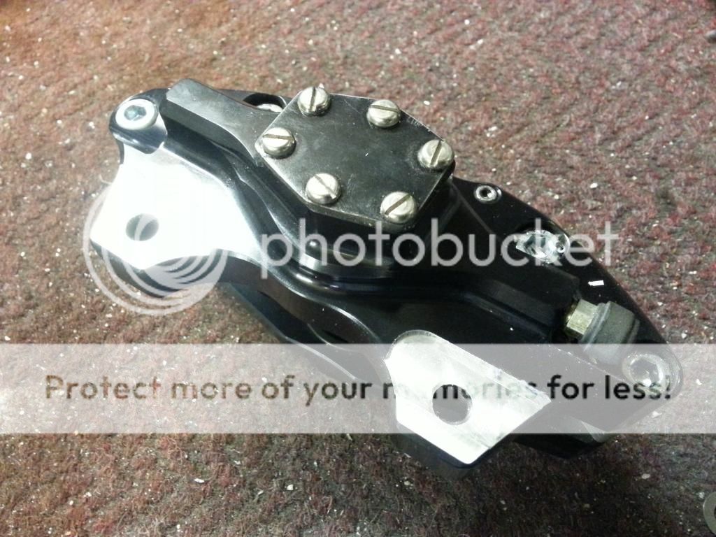
Fitted nearside outer driveshaft. caliper and brake lines.


Marking bolts when tightened for the last time has paid off. Just about to fit the outer driveshaft when I noticed that the nuts holding the bearing carrier to the vertical link had no orange markings on them. Checked and they were not tight!
Having machining toys keeps paying off. Fitted the caliper and noticed that the disc wasn't centralised in the caliper, similar problem as I had on the offside. However, taking a mm off the bracket wasn't enough so I milled a couple more from the caliper lugs.


Anothor small problem. The combination of standard circlips, bespoke driveshafts and high spec CV joints has resulted in the CV retaining circlips being too thick to fit in the amount of circlip grove protruding from the CV
I have some thinner clips somewhere and will look again tomorrow. However, as a backup I have ordered thinner ones (1.1mm compared to the 2mm standard items) in cae I can't find them.
I have some thinner clips somewhere and will look again tomorrow. However, as a backup I have ordered thinner ones (1.1mm compared to the 2mm standard items) in cae I can't find them.


Working Friday and Saturday so nothing done on car.
Today, managed to bolt in and torque up propshaft.
Also did a little fettling to the rear damper central bracket so that the dampers were in a better alignment and not rubbing the bracket on maximum droop. You may notice that I am now starting to use titanium nuts as well as bolts. They are a rather expensive extravagance but I thought, what the hell, in for a penny in for hundreds of pounds


Presently waiting the arrival of thin circlips so I can complete the assembly of the rear drivesahfts, so I thought I would go off an a slight tangent and play with the wheelie bar design.
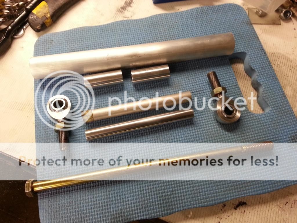
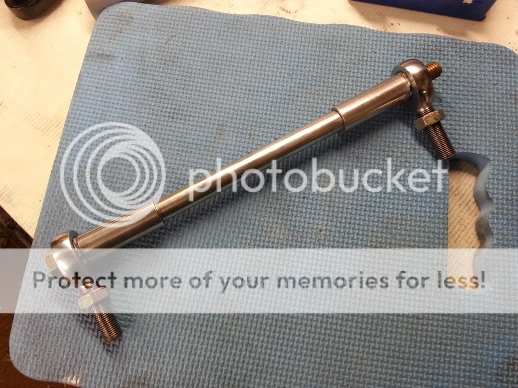
Drilled holes in chassis to accommodate the 1/2" bolt bought from the States. Made spacers out of aluminium bar stock from my collection. Using rod ends from my stock is helping to keeps costs down
Although I have boxes of nuts I couldn't find any 1/2" UNC. Fortunately I was going over to SE London yesterday for an Indian Christmas dinner with fellow car nuts and there a nut and bolt shop (Modern Screws) on the way so I picked up a couple.
As soon as carbon fibre tubes arrive I can start on the aluminim inserts that the rod ends will screw into.


Yugguy
Torque King
Can't you get her to help? Holding the other spanner while you turn the bolt?
T9 man
TC ModFather
That's a point, the dear lady might be itching to get her hands dirty on the car, she might prove to be an asset OG if only you would allow her
T9 man
TC ModFather
Oh bless her
T9 man
TC ModFather
Your probably right there Steve, but family is family and we will all get old and need help one day; I take my hat off to you sir! 
Similar threads
Similar threads

