At Last!. I have started on my car ;-) PART 2

I have been thinking (never a good sign as it usually means changes are afoot) about my lack of stiffness (well, I am getting on a bit).

The thought of cutting the body about and making lots of carbon fibre panels doesn't fill me with joy and excitement. So I have been rethinking the problem and have almost decided to go the full roll cage route instead. These photos added a little spur to the thought process:


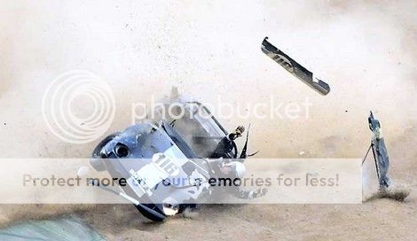
Tony Tompson are the sole supplier of the Safety Devices FIA approved roll cage and is the only one available in the UK. I found one in Europe, but more expensive and heavier. Safety Devices cage shown below:


Only issue is that the side bars sit in the void under the doors. OK on the driver's side but the passenger's side is full of silencer. As these bars are separate modifying one shouldn't be a problem.
 
I am surprised a cage of some description wasn't in the plans Steve. It would be first on my list for a build such as yours. Easy enough to modify as I did the same thing to the SD cage I had in my Chevette. I made door bars that went into the door and kissed the outer skin. Also tweaked it to clear the exhaust routing as mine came in through the cabin and exited the rear quarter.
 
I was planning to use a roll bar and one was already fitted. As the risk of a side impact is very small in drag racing and even smaller in sprints and hill climbs I didn't consider a full cage, with its extra weight, necessary. But, as I need to improve the torsional stiffness the cage will serve two purposes and save a lot of time and effort making carbon fibre panels which may not even work. I have also come to realize that the I will be safer which is no bad thing I guess. I will just have to accept the extra weight :-(
 
When I rebuilt the Chevette I used the cage as part of the front space frame when I reworked the front end to fit the V8. It made the car very rigid and was ideal for remounting the front top suspension mounts. If you had the cage tied in then the panels will be just a skin and not structural.
 
Agreed. Had a long chat with my fabricator and chassis guru yesterday and came up with a plan.

In order to maximise stiffness it will be welded to chassis. Clamps allow movement. The downside is that this will make removal of the body impossible, but I can live with that.

The weight (approx 45-50kg) hurts, but it will make the car faster and using T45 will keep it to a minimum.

As soon as engine and gearbox are back in the car I can fit the body and then start on detailed design of cage.
 
When I rebuilt the Chevette I used the cage as part of the front space frame when I reworked the front end to fit the V8. It made the car very rigid and was ideal for remounting the front top suspension mounts. If you had the cage tied in then the panels will be just a skin and not structural.


This got me thinking. By doing something like this (won't know details until engine, gearbox and body are back in/on) I should be able to lighten the chassis a lot more, ameliorating some of the extra weight :) The cage is getting to look and act like a space frame.

elanstiffeningcage_zpsba8ce049.jpg


The engine is mounted rigidly and I am looking at adding additional bracing at the front, tying in to the unused power steering pump and the alternator bracket bolt holes (ignore front suspension, this is an old photo and much has changed since then)

 
'ameliorating' had to google that!

You say the engine is mounted rigidly, so no movement in any of the mounts? What am I missing here in this particular part of the build? I'm curious.
 
Engine mounted rigidly but gearbox isn't.


As there was flex in chassis, mounting gearbox rigidly would have resulted in something breaking! Gearbox is mounted on 4 rubber bushes (ignore orientation of brackets :) )


However, with the proposed 'spaceframe' I will re-visit this mount with the view of fitting stiffer rubber.
 
Hopefully, replacement TIG welder will arrive tomorrow so that I can weld up the engine mount bracket and the engine and gearbox can go back in. Once they are back in the body will be fitted and the car will be off to the roll cage fabricators. To that end I have been doing some research on cages for the Elan and there is a dearth of info. Cages available are really for safety only and I am more interested in chassis stiffening. We will have to, as usual, work it out ourselves, but I have managed to find a few pictures of cages that we can use as guides.


Engine mounted rigidly but gearbox isn't.


As there was flex in chassis, mounting gearbox rigidly would have resulted in something breaking! Gearbox is mounted on 4 rubber bushes (ignore orientation of brackets :) )


However, with the proposed 'spaceframe' I will re-visit this mount with the view of fitting stiffer rubber.

Og in reference to the gearbox mounts instead of going for a stiff rubber could you not get a softer yet longer lasting poly bush ???
 
I have not been able to find a polybush fitted with a threaded rod at each end, as can be seen in the photo of the gearbox mounting a few posts back. If you have a source please let me know.
 
im on nights so i will have a look for you i have plenty of time for research :)

have you got a pic of the OG so i have something to reference to because i am a great one for possiabiltys

hello Og sorry ot be a pain is this the sort of thing you have for a gearbox mount , im just workign out ideas etc
http://britishparts.co.uk/products/5825-engine-mount-STC434 ( i know it not for your car)

**Edit. 3 Posts merged just to tidy up a little. TN69**
 
Last edited by a moderator:
I have just spent the best part of an hour staring at my front brake pipes. I finished the pipes a few months ago but recently noticed that, now there are some wheels on, the flexible pipes foul the wheels and upper wishbones on full lock!


However, after some intense experimentation I have found a solution which includes using the original chassis brackets which, fortunately, I haven't cut off yet :) The brake pipe will now be routed between the upright and spring. Luckily the existing pipe is too long so I can simply trim it down to a length that keeps it away from harm regardless of suspension and wheel movement. A small plus point is a slight reduction in weight due to shorter flexi and rigid pipes and the removal of two brackets used on the original setup :)

 
Reduction in weight due to brake pipe rerouting - 35gms :)

Engine mount bracket welded yesterday so the plan is to install engine and gearbox today. Update with photos tonight.
 
Have seen many pics of the Elan undergoing weight loss but none of the driver.
Due to the obsession to reduce weight I'm thinking that the driver would have to be borderline anorexic :eek: :rofl:
 
Best laid plans etc. Realised that I hadn't finished brake pipes in engine bay so did that and also shortened front flexi brake pipes. Found the nuts and bolts for the gearbox mount so I am now ready to put engne and box in tomorrow, promise :)


Rerouted flexible pipe a much neater solution

 
That is in hand. Plan is to lose a minimum of 5kg before car is finished :)

Steve I posted that being very much tongue in cheek as I realized you can't drill holes in your body to lose weight. ;):)

PS that twisted wire around the rubber in the last pic is unexpected :eek:
 
I know :) but I could do with l losing a bit of weight so will use racing as an incentive.

That was fitted by the rack reconditioners. I need to restrict steering lock to prevent wheels hitting the top wishbones so these wires will be removed so I can access the rods.
 
Lunchtime progress report.

Gearbox in. I had to modify airline to solenoid as it rested on the gearbox casing and I have ordered a clamp to pull the fuel pipes away form the box. Other than that, it went in pretty easily. Off now to fit engine.


Another one of those one step forward two steps back moments.

Looking at the engine install I realised that the fuel pipes came up very close to the exhaust, so I have had to re-route them up to the front of the engine, adding to length and weight. The pneumatic pipe for the throttle blipper was also a tad close to the exhaust but this was easy to remedy by sinply dropping it further away.

A question for the racers. I have been looking as to where I can mount the fuel pressure regulator and the obvious place is on the distributor hole plug. Are there any issues with mounting the regulator on the engine? The OEM one is mounted on the end of the fuel rail so I can't see a problem.

 
Started on the seemingly endless list of little jobs.

Clamped brake pipe to chassis adjacent to the gearbox and engine. Also connected pneumatic pipe to the solenoid controlling the throttle blipper.

 
As long as nothing silly like work gets in the way, I hope to pop over and see you next Saturday Steve if your available.
I still have your "Bah Humbug" hat in a bag in the boot to give you ;)
 
That would be great. What time are you thinking about, as I deliver parcels on Saturday? Usually finished by midday.
 
Just dodged a bullet. After making a towing eye, I decided to work out what I needed to finish the fuel system in the engine bay. Whilst poking about underneath I noticed that the return pipe (the one crossing the chassis) was touching the gearbox! Ooops! Fortunately there was enough slack to enable me to push it away. The box is almost rigidly mounted so there is very little movement. Phew :)

 
Evening update.

Met with cage fabricator this morning for another chat. Agreed on amount of tube required so that will be ordered this week. Start date has been put back to Monday week.

Discussed fuel regulator location with engine guru. He said not to mount on engine as high frequency vibrations can cause problems, so I have repositioned it on the chassis:


Fuel supply pipes are AN8, which is almost 10mm ID. The fuel rail inlet and outlet are 7mm, so I have drilled out the inlet to 9.5mm, leaving the outlet as is in order to create a restriction. 2.5mm may not sound a lot, but the cross sectional area goes from 38.5mm2 to 71mm2, an increase of 84%!

I have fitted modified pipe clamps to the fuel rail retaining bolts ready for the return pipe:


Didn't like the hole I drilled in the fuel rail union, so cut it off and will get the correct size welded on tomorrow, along with the rest of the solid fuel line unions that need to be welded on. This has the added advantage of increasing the cross sectional area by 105% over the original :)

Knocked up a towing eye yesterday and bolted it to the chassis today. Don't worry, even if it is aluminium it will only be fitted when required :)


Fuel pipe connectors welded on this moring so full steam ahead.


This is the union I had trouble sourcing:


Something seems to be missing....... Oh, yes, 8 injectors :)


Similar threads


Please watch this on my YouTube channel & Subscribe.


Back
Top