Rhythm - Late 60's Inspired Sports Car

Hi guys!

My name is Nick. I've been into hot rods and custom cars since I was a kid. For over 10 years, I've been learning the art of metal shaping starting out with a set of about 9 hammers, some dollies, and a 3/4" rubber mat and things have kinda evolved from there.

I'd like to extend my hand in appreciation to all the members who have the same passion for cool cars and enjoy taking the time to share their knowledge and experiences.

I was hoping to share a completed project built entirely from scratch out of steel that both my dad and I are quite passionate about. This got me hooked on fabricating.

I'll post one photo, if you guys feel it's "too out there"...it'll be removed.

INVRTMD-322.jpg


Thanks very much!
 
Impressive, especailly since all the panels were made from flat steel and hammered into shape. What is the car based on chassis wise?
 
Impressive, especailly since all the panels were made from flat steel and hammered into shape. What is the car based on chassis wise?

Thanks very much Waynne. Really appreciate the thumbs up.

The chassis was also built completely from scratch...but before I get into that, maybe I should probably give a little [FONT=verdana, arial, helvetica]background on what inspired me to start creating this vehicle when I was around 16.

Basically one evening, my dad and I began discussing whether to keep searching for a 50's/60's vehicle to customize or ... an idea totally off the wall.... venture out and build something from scratch. We were having a hard time finding something cool to bring home and customize so this lead us to sketching out a few conceptual drawings for a custom mid-engine vehicle.
[/FONT]

Some styling cues were borrowed from classic European sports cars as well as American muscle cars of the late 60's..thanks to all the photos I was collecting over the years. The SR-71 Blackbird played a key role with regards to the shape of the vehicle - such as the concave surfaces flowing from the front fenders and into the turbos...my dad is really into planes and jets. The interior design was based loosely around a fighterjet cockpit. Our goal was to create something that may have resembled a factory produced elegant supercar in the 60's.

A shot of the SR-71 depicted on the car's show poster.
INVRTM-SR71.jpg


Then the fun began - building the car. By this time I was 19/20...for the prior 3 years after my homework was completed...of course :p... I would sketch out ideas, learned how different suspensions worked, studied chassis designs... and so on. I still have the 3" binder full of this information I scrounged(from the library since the internet wasn't that mainstream back then) as well as a Chilton's Automotive repair manual covering vehicle repairs from the late 50's and 60's. My dad insisted that this was an important step prior to tackling such a project...

So, under his guidance and with the limited tools I had available to me I learned how to shape metal, weld, do bodywork, and paint. I had some experience repairing our own vehicles, but not to the degree required in creating an entire car. That came from just picking up the tools and getting into the work.

A few more photos.
INVRTMC-1302.jpg


INVRTMC-1172.jpg

Cockpit inspired interior

INVRTMC-1362.jpg

Upper turbo scoops used for the cold air induction...the 365HP engine loves all that extra air :D The front of the engine(pulley end) is facing the rear of the vehicle...for better weight distribution towards the center of the car.

Now, in regards to your question about the chassis...

The chassis was designed and fabricated from scratch. DOM tubing was bent into a full length frame - 2 continuous rails per side(stacked one over the other with a web in between) to create an I-beam effect. A FWD engine cradle from a mid-size vehicle which had the lower A-arms and sway bar already incorporated into it was mounted in the rear with Thunderbird McPherson struts utilized for the rear suspension. Rhythm's front suspension uses a twin A-arm setup with manual rack and pinion for steering.

INVRTMC-362.jpg

The DOM tubing provided the perfect opportunity to eliminate cooling lines between the engine and rad by running the coolant within the frame itself.

Thanks for looking. More to come...
 
Impressive work there and you do have a certain skillset. Not loving some of the styling but that's a minor personal taste issue considering what you have achieved. It is safe to say it is pretty unique and definately has the 60s feel about the concept.
 
That is one totally radical looking car you have there! I applaud the skills that went into it ;)
 
Impressive work there and you do have a certain skillset. Not loving some of the styling but that's a minor personal taste issue considering what you have achieved. It is safe to say it is pretty unique and definately has the 60s feel about the concept.

Thanks Stamford and I appreciate your honesty...no worries. :D

There are certain design elements that I would have liked to change as the end of the build was approaching ... but it's a project that I wanted to see through to the end. We set a 60's sports car theme for the build...and along the way there were some changes to the styling from the initial concept...but if one keeps making changes...the project would never get finished.

Rhythm was completed in 2008 and licensed as a fully functional road vehicle.

After taking almost a year off...I decided to start "the next one". While I am quite pleased with the way Rhythm turned out...I wanted to make some changes to the styling. And the most effective way of modifying the body would be to hand craft another one. Simply called R2...this is a fresh sheet of paper design, LS6 powered, 500+HP mid-engine sports car metal crafted again from flat sheet metal and loosely resembles Rhythm. However, the major difference comes in the overall tightness of the proportions resulting in a very modern appearance. Rolling on 275/35/R18s in the front & 315/30/R19s rear R2 is 28” shorter, 6” narrower, and a little over 900lbs lighter.

I invite you to check out the build progress on my facebook site: http://www.facebook.com/iNVisionPrototypes

The body panels have all been shaped and now it's time to weld them all together.

Thanks again,

Nick
 
INVRTMC-372.jpg

16Ga sheet metal formed to create the rear inner fenders. The factory 'caps' that the McPherson struts bolt into were blended into the surrounding metal.

INVRTMC-382.jpg

Primered and ready for paint.

INVRTMC-392.jpg

All painted and assembled. A trunk was incorporated into the design behind the temporary V6 engine.

The car ran with the he transverse V6 until the SBC 350 was ready, then it was deep 6'd. This little change made putting your foot into it a little more fun...at the expense of a much smaller trunk. To maintain Rhythm's theme I picked up a hot rodded Chevy 350 and mated her to a Caddy Seville TH325-4L trans(4spd). The added weight and shift in weight bias within the car was a large concern. So with specific component upgrades, mounting the engine in a reverse rotation manner (pulleys facing the rear) and pushing the engine to the front as far as possible without compromising the CV angles we were able to fit the powerplant in quite nicely.

With any project, as I'm sure many know there is always a tweak here and there. In this case, there were 4 major tweaks...first, we had to create a BOP plate to connect the trans to the engine...which wasn't too bad. Second, with the unit sitting backwards, we ended up with 3 reverse gears and one forward gear! Wild huh? So, that meant flipping the differential 180* though the use of another adapter plate. The other added benefit was that it lowered the unit by 1.375"...lower centre of mass is always an added benefit. In doing that though, the stub shaft had to pass though between the crankshaft journals. Even wilder huh? This lead up the the 3rd tweak whereas a hole was made in the oil pan, sleeved, and therefore allowed the shaft to pass through. When the oil pan is installed there, the sleeve has 3/16" clearance between it and the journals that move past it. Correct spacing was accomplished by carefully measuring the distance from the rear of the engine block to where the centre of the stub shaft was to be. Then the adapter plate with specific thicknesses were created to get the spacing just right... and finally 4th, the design and fabrication of a set of reversed headers.

Here are some of the initial pictures of the mock up.

ChevyCadPower1.jpg

After the rear BOP plate was created ... I needed a set of heads.

ChevyCadPower2.jpg

As mentioned above, adapter plate thicknesses played a crucial role in centering the drive axle between the crank journals...definitely followed the "measure 3 times...cut once" rule here.

ChevyCadPower3.jpg

All together and bolted. Unfortunately not a runner yet... :sad:

INVRTMDSCN53852.jpg

Some math to get the centre of mass correct...

INVRTM5562.jpg

In about an hour everything was stripped out and clearanced for the new engine.

INVRTM5567.jpg

Trimming out the old mounts...

INVRTM2484-2.jpg

You see what I meant about the stub shaft...going right though the oil pan...directly between the crank journals.

INVRTMC-402.jpg

That Edlebrock air breather was changed out for the cold air induction unit I fabricated.
 
INVRTMC-1342.jpg

Did a little tuck shrinking to create the housing's shape.

INVRTMC-1352.jpg

Shaping and scribing the duct attachments.

INVRTMC-1362.jpg

After welding it up, it's mocked up in the vehicle...now its time for some primer and paint.

When the top turbo fans are switched on, the engine loves it... all that extra cool air.

Thanks for looking! Hope you guys have a great weekend! More to come...
 
Interesting posts, make for good reading! Maths! Hate it! Love the axle solution, is it running a wet sump still? Any issues at all with the work done?
 
Marvellous work that! Your duct attachments proposal has given me an idea?
I hope you don't mind if I borrow it ;)
 
.... is it running a wet sump still? Any issues at all with the work done?

Yeap, the oil pan is sleeved to allow the stub shaft to pass through...it's really tight :D.

We've got a little over 4000km on the car...including 3000km on this power plant and aside from carburetor tweaks she runs great! The upper concave surfaces really contribute to the downforce applied to the car...as speed increases. Very cool feeling when driving.
 
Marvellous work that! Your duct attachments proposal has given me an idea?
I hope you don't mind if I borrow it ;)

Ideas are great...carrying them out is the hard part :D I don't mind sharing the design at all. If you have any questions let me know.

What are you working on?

Cheers!
 
Ok...here goes the exterior sheet metal segment of Rhythm's build.

As a precursor to the pictures, the only tools I started with to shape the steel panels was a set of about 9 hammers(you'll see them hung up in some of the photos), some dollies...creating more as were required, and a 3/4" rubber mat. Unfortunately at the time, I was unaware of Lancaster shrinker/stretchers, English Wheels and planishing hammers...they would have made life soooo much easier.

INVRTMC-442.jpg

The turbos were created by first rolling the sheet metal over a large PVC pipe...then planishing the material with a hammer and dolly to stretch it and give it the convex curve. To smooth out the highs and lows, the turbo was sanded with a long board to illuminate the highs ... followed by more hammer and dolly work.

INVRTMC-452.jpg

This was created using a very primitive english wheel that I built using two truck bearings shown below...

INVEW-FIRST2.jpg


In an effort to speed up the process I was wondering if two steel wheels, one with a crown...the other flat, would produce the same result as me stretching the metal by hitting the hammer against the dollie in a longitudinal direction. After scrounging some bearings, box tubing, and utilizing the adjuster on our press I came up with this crazy machine.

And while there were some serious drawbacks like the height between the anvil mount arms, and the extremely narrow point of contact ...it worked! Yes, there was some tracking in the pieces...but most of them were smooth out running perpendicular with really light pressure...and the remainder with the good ol' hammer and dollie.

INVRTMC-462.jpg


INVRTMC-472.jpg


INVRTMC-482.jpg


INVRTMC-492.jpg

Yes, that was a Jag bonnet, that was cut up and 'readjusted' for a more aggressive appearance.

Thanks for looking.
 
Last edited:
On a technical note, how did you lose the rivets and seams?

There are no rivets used to join any of the panels on any bodies we build.

In regards to the panel seams you see here is the basic process used to join them.

Once the panel is shaped and fitting the body the way it needs to, the edges are marked/scribed with either a Sharpie or very sharp awl. Excess material is then trimmed away so that the edges match. Clamps are then used to hold the two edges together and MIG/TIG welder is used to join the edges. Once the panels are welded, a grinder is used to grind off the top of the weld so that it's about the same height as the panels on either side. If any warping happens from the welded area being heated, a hammer and dollie is used to stretch the material. Upon doing this to join all the panels, some bondo(plastic filler) may be required to hide the seams, though this isn't preferred. Primer is finally applied...body is sanded and painted...

You will see more examples of this once I get a few minutes to get more photos up.
 
INVRTMC-502.jpg

All the pieces for the fascia cutout and prepped. Each piece had the 5/16" edge/lip tipped over a custom shaped anvil with a hammer. It was truly a difficult task(at the time) to create a consistent edge that could be butt jointed with the next piece. You can also see how much more length was added to the bonnet not only by staggering it, but also by adding the piece at the rear. The pivots created to flip the bonnet forward were tucked in under the fascia(the yellow things).

INVRTMC-512.jpg

Flirting with a new feature out of cardboard to flow the front scoop into the headlights.

INVRTMC-532.jpg

The DOM frame can just barely be made out ... inside the front scoop.
 
Last edited:
Continuing on with the build process...

INVRTMC-542.jpg

Creating the upper faux scoop for the front hood...something I'd now form out of one piece.

INVRTMC-552.jpg

Hood all welded up and headlight surrounds being fitted.

INVRTMC-562.jpg

At this stage I believe we were getting ready to finish bringing the bumper feature around the corner.

INVRTMC-572.jpg

Looking back...I can only remember all the hours of welding and hammer/dollie work...

INVRTMC-582.jpg

Gapping the trunk lid with the body.
 
Ideas are great...carrying them out is the hard part :D I don't mind sharing the design at all. If you have any questions let me know.

What are you working on?

Cheers!

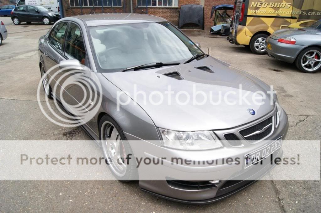
I have a humble Saab 9-3 with carbon fibre Naca ducts cut into the bonnet.
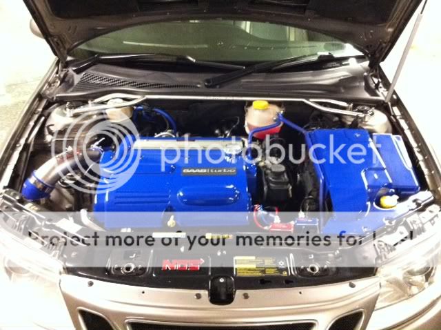
I was thinking along the lines of a similar looking arrangement to your ducting system, hopefully with some polished flexipipe going up to the louvres to bring more air down into the induction system. Have some more working out and measuring to do first though.

1st pic shows the Naca bonnet ducts and the 2nd shows what I have to build around in the engine bay.

Neowork7.jpg

p11.jpg
 
I have a humble Saab 9-3 with carbon fibre Naca ducts cut into the bonnet.

Sweet looking ride! Sexy lines :D

Looks like its gonna be a great project. How much room do you have between the bonnet and the top of the engine. Can place some 'Play-doh' or mold-able putty between the two in specific areas can give you pretty accurate dimensions. May also have to determine the maximum tilt on the engine when you're running it so it doesn't push the ducts into the bonnet upon acceleration.

Have fun :bigsmile:
 
Not much space under the bonnet, I do however appreciate the tips you have just given me - invaluable! ;)
 
Makes my humble body mods fade into insignificance.

Rear styling I like, front not so keen. There is a hint of Jaguar in the front bonnet lines.

The photo showing the chassis has me a little concerned. Has any triangulation been added between the two chassis rails to resist twisting under torque loadings, or is the body being used as a stressed member?
 
Last edited:
... a hint of Jaguar in the front bonnet lines.

The photo showing the chassis has me a little concerned. Has any triangulation been added between the two chassis rails to resist twisting under torque loadings, or is the body being used as a stresed member?

Old-Git, you've got a great eye. :D Yes, the bonnet has a section of a Jag's bonnet in it. We reproportioned the original bonnet for a more aggressive appearance. The Jag bonnet fit the design well...except for the fact that it was too straight and flat.

As for the chassis, triangulation and eliminating longitudinal twisting was our primary concern when designing and fabricating it. I didn't want to rely on the body as a stressed member...even though it does act as one.

You can put your concerns at ease. If you look very closely in the next photo...

INVRTMC-392.jpg


... you will see triangulation plates in the corners of the 4 main diagonals which are tied in from side to side with spreaders. In regards to the web between the DOM, it is welded on both sides essentially creating an "I" beam. Lifting any corner of only the chassis or both vehicle/chassis together...for instance the front right in a static/dynamic motion... will result in the front left side reacting at exactly the same moment with no deflection in the frame.

Thanks for looking. I appreciate you taking the time to analyze the chassis' fabrication methods.
 
Last edited:
Set expression to smug mode :-)

I am surprised that there is no twisting of the middle section of the chassis. No, not suprised, amazed.

By triangulation, I am thinking of actual bars/tubes crossing the middle part of the chassis diagonally as I can't see what stops it from twisting at this point, unless it is the steel body.

I am not doubting what you say, just find it hard to believe looking at the photo.

How much does it weigh?

I like the wheels, old style slot mags are my favourite and they also hide the suspension. I will be fitting similar wheel to my project.
 
Last edited:
No worries Steve. :bigsmile:

And I understand where you are coming from. A lot of thought went into engineering this frame to keep it light yet very strong for a mid-engine mounted powerplant. Triangulating all the inside corners of the main frame diagonals with 1/4" plates(also acting as the cab mounts) in addition to the cross members is more than sufficient as it traps them from experiencing any flexing.

Saying that, the steel body does provide strength to the chassis...but I didn't want to rely on it as a stressed member - especially when all the bonnet, boot, and door gaps are 3/16"(3.5mm). In 3 years and 4000+km since it was built(except for some road rash) the body doesn't have a single chip/crack in the gap areas. Criss-crossing the frame with additional tubes becomes redundant and adds unnecessary weight - consider it over engineering the frame. When running the car, it corners like it's on rails.

Now, if the engine was located in the front and driving the rear wheels...then yes there would definitely need to be additional reinforcement to remove the torsional flexing. Here the powerplant is mounted in it's own sub-frame...which is then mounted to the main chassis using poly-urethane mounts to dampen any road noise. On a side note, the entire powertrain can be dropped out of the car in 20min if I need to perform any significant work on it. The bare DOM chassis comes in at just under around 180lbs.

The entire vehicle with a full tank of gas and me out of it weighs in at 3675lbs...not too bad...but lots of room for improvement.(R2 will be around 900lbs less :D)

Those Asen wheels were tough to get...getting quite scarce around here. I tried 18s with the design... however, they just didn't give it the right feel for a late 60's inspired ride.
 
Last edited:
INVRTMC-592.jpg

Here is the body just prior to the high build 2K primer stage. The signal lights still needed to be finished. Some of the welded joints where skim coated with MarGlass...a fiberglass reinforced body filler prior to primer. I'm sure some will dispute this, but speaking from experience nothing beats bondo or MarGlass adhering directly to metal when properly prepared.

INVRTMC-602.jpg


INVRTMC-612.jpg

Before skinning the doors some trick mirror brackets were developed to raise the mirrors over the turbos. They're held on with a single hidden fastener and conceal the wire for the power mirrors. From this picture you can see how the front door gap curve comes out into a horizontal plane. Days were spent to make it open WITHOUT binding. Moving that curve even 1/8" forward or back didn't allow the door to open.

INVRTMC-622.jpg

P/S completed ... and matches the drivers side. Preparing to attach the flute feature to the turbo. Later a one-off marker light will be installed into this area.


INVRTMC-632.jpg

Another perspective of the rear. Laying out for the flute feature on top of the turbo. Sitting on the roof is the interior ceiling liner... the only glass panel created for the car.

INVRTMC-642.jpg

Backup light mounted as well as bumper feature created and finished. Learned the tuck shrinking procedure through some experimentation when creating the bumper corners...tho I didn't know what it was called back then. The rear deck has a placement for sequential signal lights. It's kinda hard to make out but some torch shrinking took place to rid the upper deck of some oil canning. Filler being applied to clean up the jams.

INVRTMC-662.jpg

After the initial coat of high build primer, the body was guide coated again...and blocked out. Then an additional coat of high build applied in the lows.

Thanks for looking.
 
continuing on...

INVRTMC-672.jpg

I'm applying the 3rd and final coat of red dyed high build. Yellowish(not dyed) was the first, then the purple(happened to turn out that way after using up some old bases), then the red.

INVRTMC-682.jpg


INVRTMC-692.jpg


INVRTMC-702.jpg


INVRTMC-712.jpg

Giving the arm a break...

__________________
Nick M.

A journey in design and fabrication begins with a vision, a single pen stroke ... and in some cases the blow of a hammer.

Some projects: http://www.facebook.com/iNVisionPrototypes
 
Last edited:
i take it the difference in colour was to see the difference when rubbed down ?

Exactly! The primer was dyed not only to help in block sanding, but also to make the difference between the final colour and primer the least as possible...in the event the paint gets chipped. If the final colour went orange..the primer would have been dyed orange.

Hours upon hours of block sanding went into getting the panels perfectly straight...at first in the metal stage...then in the high build primer stage. In the metal stage..the bare metal was shot with primer and then sanded to reveal the highs and lows so that they could be hammered accordingly. When it got to primer, it was repeated 3 times before the base went on.

Thanks for looking.

__________________
Nick M.

A journey in design and fabrication begins with a vision, a single pen stroke ... and in some cases the blow of a hammer.

Some projects: http://www.facebook.com/iNVisionPrototypes
 
Last edited:
here are some more...

INVRTMC-742.jpg

Three coats of base were applied...

INVRTMC-752.jpg


INVRTMC-732.jpg


INVRTMC-762.jpg


INVRTMC-772.jpg

...followed by 4 liberal coats of clear to create that 'deep' paint job.

I do have to say that making the transition to the B/C paint system from the single stage urethanes had a fairly easy learning curve...applying the clear was a little tricky at first...Taking my time and just watching for that 'flash' resulted in non of those evil runs and sags. Saying that, I did take the paint finish to the next level after learning how to cut and polish the clearcoat.

Thanks for looking...next photos I think will be on fabricating the interior.

__________________
Nick M.

A journey in design and fabrication begins with a vision, a single pen stroke ... and in some cases the blow of a hammer.
Some projects: http://www.facebook.com/iNVisionPrototypes
 
Last edited:
Hard to believe how much manual work has gone into that once the paint is on. Looks flawless from the photos.

Thanks very much.

Once all the welded seams were smoothed out...it was almost a shame to cover them up with the high build primers. But I was really set on painting it, so it had to be taken to the next level. I'd say that in addition to smoothing out just the metal for a smooth finish...an additional 1500hours went into block sanding the primer before the vehicle even saw paint.
 
that is beautiful, once its been cut and polished - remember and wait till the paints cured or been baked at least - get some pics taken outside

Thanks buddy!

Yeah, since I don't have a heated booth I waited about a week for the paint to cure before cutting it. Still wanted it a bit soft to aid in the polishing process.

I have some outdoor photos on the first page and was going to finish posting the build photos before finishing up with the completed ones in the end. But, here is a bit of a teaser.

INVRTMC-1322.jpg


and yes, in case someone was wondering if both sides are symmetrical...they are :blink1:

Thanks for looking!
 
It's been a busy past week. Finally had a chance to get some more photos up of Rhythm's construction progress. Here's the trim work segment.

All the trim started from 1"x2" solid aluminum stock.

INVRTMC-782.jpg

Front Grill & Side Turbo Scoop Surrounds: The some of the 1"x2" aluminum stock was run though the table saw and ripped into 1"x0.25"x28"LG bars. These bars were then curved by hand(24" adjustable wrench and 2lb sledge) to the required shapes as illustrated with templates.

INVRTMC-882.jpg


INVRTMC-872.jpg


INVRTMC-862.jpg


INVRTMC-812.jpg

Side Flutes: 1"x2" aluminum stock was cut to the approximate lengths required. Short stubs were then welded onto the ends at right angles. These pieces were then clamped in the mill using a custom jig. Using a router bit, the excess material was trimmed away leaving a rough triangular shape.

INVRTMC-822.jpg


INVRTMC-832.jpg

Trim in various stages of completion. Final shaping of all the pieces were done with a rasp, followed by progressively finer files, sand paper and buffing machine.

I recall I had one of the final pieces sitting on the bench in front of me as a reference while I was hand shaping another. A buddy dropped by and got watching what I was doing. He picked up the completed piece and asked...where I bought the trim from. Taking a step back, I simply pointed to the piece clamped in the vice that was being worked on.....

INVRTMC-842.jpg

After taking so much time and care in making them laser beam straight...they were cut.

INVRTMC-852.jpg


__________________
Nick M.

A journey in design and fabrication begins with a vision, a single pen stroke ... and in some cases the blow of a hammer.

Some projects: http://www.facebook.com/iNVisionPrototypes
 
Nice to see some 'handyraulic' machine work going on! When I was an apprentice I would have got a slap for milling with the quill extended!
 

Please watch this on my YouTube channel & Subscribe.


Back
Top