You are using an out of date browser. It may not display this or other websites correctly.
You should upgrade or use an alternative browser.
You should upgrade or use an alternative browser.
At Last!. I have started on my car ;-) PART 2
- Thread starter pgarner
- Start date
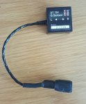
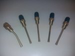
This sensor is only 1-Axis so isn't any use :-( Back to the drawing board.
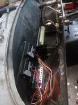
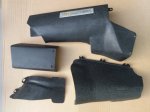
ECU and PDM brackets finished, although it took me three attempts before I got the front part of the ECU bracket the right width. The holes are to allow ventilation to the ECU heat sink (Yeah, right) and the reduction in weight of 6gms is purely coincidental There are a lot of pin holes in the laquer but they are out of sight so they can stay. My carbon skills are just enough to produce strong and workable parts. I have yet to tackle exposed weave parts that will be on show as this takes more skill and patience than I currently possess.
These will be attached to the bulkhead using a flexible glue and rubber strips in order to reduce vibration.
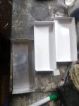
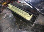
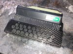
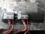
ECU and PDM brackets finished, although it took me three attempts before I got the front part of the ECU bracket the right width. The holes are to allow ventilation to the ECU heat sink (Yeah, right) and the reduction in weight of 6gms is purely coincidental
These will be attached to the bulkhead using a flexible glue and rubber strips in order to reduce vibration.


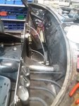
I had planned, originally, to secure the glove box door with velcro. However, this proved to be not very successful so I had a rethink. I thought about fittng a hinge (as can be seen on the bottom of the door) but decided that it would get in the way.
Then a freind mentioned the Rare Earth Neodymium Magnets he was using on his project (not car related). Hmmmmmmmm, I thought, so I bought some N52 Grade 20x 2mm Disc Rare Earth Neodymium Super Strong Industrial Magnets and used 15 to hold the door on.
10 you can see in the video plus 5 more inside the glove box behind the 5 that are visible.
Seems to work OK, test will be when car is used in anger.
Genius idea love the magnets, so simple.
Can you combine 2 sensors to get 4 axes
Can you combine 2 sensors to get 4 axes
Last edited:
4th axis would be time, which could be useful 
As this is a 1-Axis unit I could fit another and get 2 but they are over £150 each new! However I have found a 2-Axis unit in America for $149. There is no rush as I will get the loom made with this and the damper position sensors in mind.
As this is a 1-Axis unit I could fit another and get 2 but they are over £150 each new! However I have found a 2-Axis unit in America for $149. There is no rush as I will get the loom made with this and the damper position sensors in mind.
T9 man
TC ModFather
Nice one Steve 

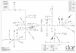
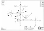
The car came back from the wiring place on Monday. The design is almost done but I lost my building slot. They have an LMP (Le Mans Prototype) car coming in for a 5 week build so I have been put back until that (far more important) job has been completed.
Disappointing, but we have made quite a few changes and working out how to accommodate the plethora of sensors along with the nitrous strategy has taken time. Not all is lost, however. I am working on adding the nitrous strategy switch to the steering wheel so the wiring for this section can be built ready for when the car returns (hopefully in early December). Also, I can get on with the bodywork.
Re the nitrous switch, David gave me a 6 postion switch but no knob, so I have just knocked one up on the lathe and mill. It looks rather large in the photo but that is due to perspective
 The labels will probably be yellow when printed on to vinyl.
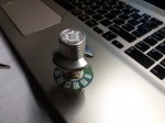
Disappointing, but we have made quite a few changes and working out how to accommodate the plethora of sensors along with the nitrous strategy has taken time. Not all is lost, however. I am working on adding the nitrous strategy switch to the steering wheel so the wiring for this section can be built ready for when the car returns (hopefully in early December). Also, I can get on with the bodywork.
Re the nitrous switch, David gave me a 6 postion switch but no knob, so I have just knocked one up on the lathe and mill. It looks rather large in the photo but that is due to perspective


Great work. Love the custom knob - it'll really suit the car.
Thanks. I have shortened the knob slightly so it isn't quite so tall.
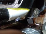
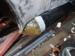
I have now fitted the exhaust silencer and working on the heat shield. The ends will be finished with carbon fibre covers.I will make these as soon as the cover shape and location is finalised and secured.
Exhaust box secured:
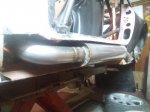
Cover loosely sitting in place:
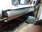
Views of each end. End caps need to be made to tidy these area up. The front cap will be vented in order to increase the air flow thereby helping to reduce the heat permeating into the car's interior:
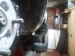
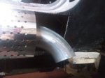
wizzer
Road Burner
Awesome work. Longing to see the finished car.
You still working on this through the winter months or do you switch to more planning and research? I seem to imagine you have a fully heated man cave with all the modern conveniences on hand to work in.
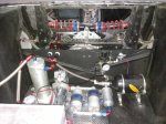
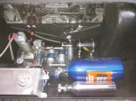
As I have a nitrous kit lying around it would be rude not to fit it 
The plan was to use it to reduce/eliminate turbo lag. However, my engine guru reckons that the engine/turbo/ECU setup I have will almost totally eliminate lag on its own. But as I have started I might as well finish. Initially planned to run one nitrous injector prior to the throttle body but, after talking to Bob Hatton who provided by first kit way back in the 70s, I have now decided to go direct port injection. I will do this with injectors fitted into the plenum spraying directly into the inlet trumpets. This is both the easiest place to drill and tap and it removes any turbulence in the inlet tract caused by the injectors poking into them.
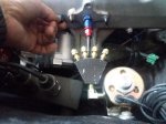
Made a couple of distribution manifolds and have gone with the fan design as this allows me to keep the pipes as close to the same length as possible.
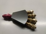
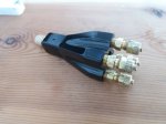
I have made one injector with three to go.
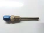
The plan was to use it to reduce/eliminate turbo lag. However, my engine guru reckons that the engine/turbo/ECU setup I have will almost totally eliminate lag on its own. But as I have started I might as well finish. Initially planned to run one nitrous injector prior to the throttle body but, after talking to Bob Hatton who provided by first kit way back in the 70s, I have now decided to go direct port injection. I will do this with injectors fitted into the plenum spraying directly into the inlet trumpets. This is both the easiest place to drill and tap and it removes any turbulence in the inlet tract caused by the injectors poking into them.

Made a couple of distribution manifolds and have gone with the fan design as this allows me to keep the pipes as close to the same length as possible.


I have made one injector with three to go.

You still working on this through the winter months or do you switch to more planning and research? I seem to imagine you have a fully heated man cave with all the modern conveniences on hand to work in.
The man cave is a barn, which is draughty but I have heat and light but no water.
Thanks. I have shortened the knob slightly so it isn't quite so tall.
Come on Steve and fess up and admit the main reason you shortened it was to reduce weight

PS have been following the Elan build for too long to have the wool pulled over my eyes

Come on Steve and fess up and admit the main reason you shortened it was to reduce weight
PS have been following the Elan build for too long to have the wool pulled over my eyes
You have lost me there, Rad, shortened what?
Thanks. I have shortened the knob slightly so it isn't quite so tall
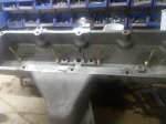
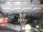
Drilled and tapped plenum for nitrous injectors. All nitrous pipes are equal length, not essential but allows nitrous to reach each cylinder at the same time. One of those rare jobs that was easier and quicker than expected. One bonus was that the aluminium was thicker than I thought so I didn't need to get additional material welded on.
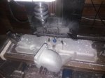
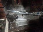


Sorting out exhaust heat shield. Centre section is bolted on and the end covers will be made in carbon and bonded to the body. These are the pucks over which the moulds will be formed.The centre section will slip under the front cover and over the rear cover. Hopefully I will be able to remove the exhaust without making too may mods but I won't know until the covers are made and tacked in place. Fingers crossed.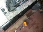


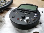
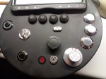
Steering wheel finally finished. All wires in connecting cable used up and no room for any more switches anyway 
Screen contains all road legal warning lights plus speedo and tacho along with outputs from the numerous engine sensors. Switches are for the linelock, launch and traction control, nitrous activation, ECU map strategy options, parachute (with keyed activation and warning lamp), fire extinguisher, gearbox neutral and indicators. The four black buttons control the various screen pages.
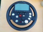
Screen contains all road legal warning lights plus speedo and tacho along with outputs from the numerous engine sensors. Switches are for the linelock, launch and traction control, nitrous activation, ECU map strategy options, parachute (with keyed activation and warning lamp), fire extinguisher, gearbox neutral and indicators. The four black buttons control the various screen pages.

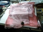
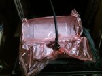
Well, that was almost an unmitigated disaster.
Easy bit - Mould came off the car fairly easily and fitting 2 layers of prepreg was a breeze. Wrapped up, vacuumed and cured at 120 deg C for an hour.
curse word bit - Getting carbon out of the mould was a nightmare, should have taken a few minutes but took me over an hour. No idea why, mould was prepared properly and had 8 coats of release agent. Had to get heavy handed and it is just as well that I hadn't planned to make multiple parts with the mould as the gel coat is destroyed. Also fortunate that I paint my carbon as the surface is f**k*d.
But at least it seems to fit pretty well. Once it is trimmed it will be fine, honest!
Hopefully the smaller front cap will be easier.
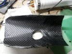
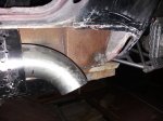
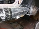


Exhaust box, what exhaust box?
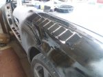
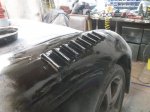
Nowhere near finished, a lot of sanding and blending in still to do, but the basic shape is there. Before you ask, the weight of the fibreglass removed from behind the carbon end caps weighs more than the caps by approx 300gms, so adding parts whilst adding lightness, a win-win
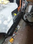
Nowhere near finished, a lot of sanding and blending in still to do, but the basic shape is there. Before you ask, the weight of the fibreglass removed from behind the carbon end caps weighs more than the caps by approx 300gms, so adding parts whilst adding lightness, a win-win

With all this lightening surely you will have to add some aero to keep this weapon on the ground
Hi Rad.
I have a front splitter. I have also designed a rear wing if required. It will be a case of gradual increases in speed and monitoring stability, handling etc whilst both accelerating and braking.
Make haste slowly seems like a good plan
I just want to still be here to see and a applaud your achievements when you reach your goal
Hang on in there, Rad, I am working as fast as I can
T9 man
TC ModFather

Sanding and body prep does seem to take forever!
Did you wet it after sanding it and use a bright light to spot the imperfections - a paint sprayer I know gave me that tip so save having to do lots of coats, between remedial sanding.
Did you wet it after sanding it and use a bright light to spot the imperfections - a paint sprayer I know gave me that tip so save having to do lots of coats, between remedial sanding.
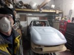
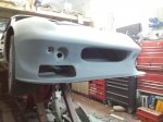
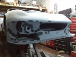
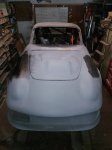
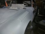
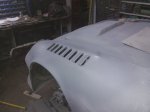
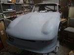
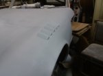
I am not looking for a car show finish. The front end is the puck for the mould for the carbon one piece front so a smooth finish will be fine. The body of an Elan is a collection of compound curves, not a flat panel to be seen apart from the rear panel that holds the rear lamps. The main problem with sanding fibreglass is when to stop. With metal you can only go so far, but with FG you can carry on sanding until you reach the other side 
Similar threads


