At Last!. I have started on my car ;-) PART 2

I've finally read every post in this thread. It looks like VR has been good for the car!

I can still recall your photos on the wall in the office, and I have to say I'm impressed with the progress and hope to come and see it campaigned when (and that is when, not if) it is. It'll probably be quite impressive to me just revving up on the drive, to be fair!

Well done, Steve.

P.S. I have to ask, what are you hiding on the side of the trailer a few posts, back? Or did you just think it would look better with the Lotus on the side?
 
VR? Virtual Retirement? :)

Thanks Iain. Hopefully the engine will be fired up this year and racing next.

P.S. :) The trailer has Stock Car Racing on the side so it needs to be resprayed. Initially I will just spray it white but if the car lives up to my hopes and expectations I may get a photo of the car racing put on the sides :)
 
For those who have never enjoyed the trials and tribulations of building a car from scratch (and that included me before I started this project) this is just a very small snapshot of some of the jobs that, although small, still take time. And there are many, many more to do.

I spent two hours replacing the rear copper brake pipe as I wasn't happy with the route it took (still not brilliant but it is better) and making a bracket to hold the parachute solenoid. Simple jobs but they still take time.

 
Has the parachute arrived, yet?

I was watching top fuel dragsters on Santa Pod's YouTube channel and one of the chaps was saying that when the parachute initially opens they lose 100MPH in 1 second, which sounds a lot to me, but some of those cars are going 200MPH+ at the line so they have to slow down quite quickly!
 
I brought it back from the States last September :)


It is only there as a safety device as the slow down part of the track is 1/2 mile long.
 
Fitted brake pads today. On the front I couldn't get one side in as one of the pistons was sticking out and I couldn't push it back. Eventually discovered that the brake hose fitting was stopping it! Need to change these. Rears were fine. You may have noticed that the pads metal backing plates have been skimmed by approx 2mm, saving 400gms. I also waisted the pad securing pins. Anal? Me? Never!
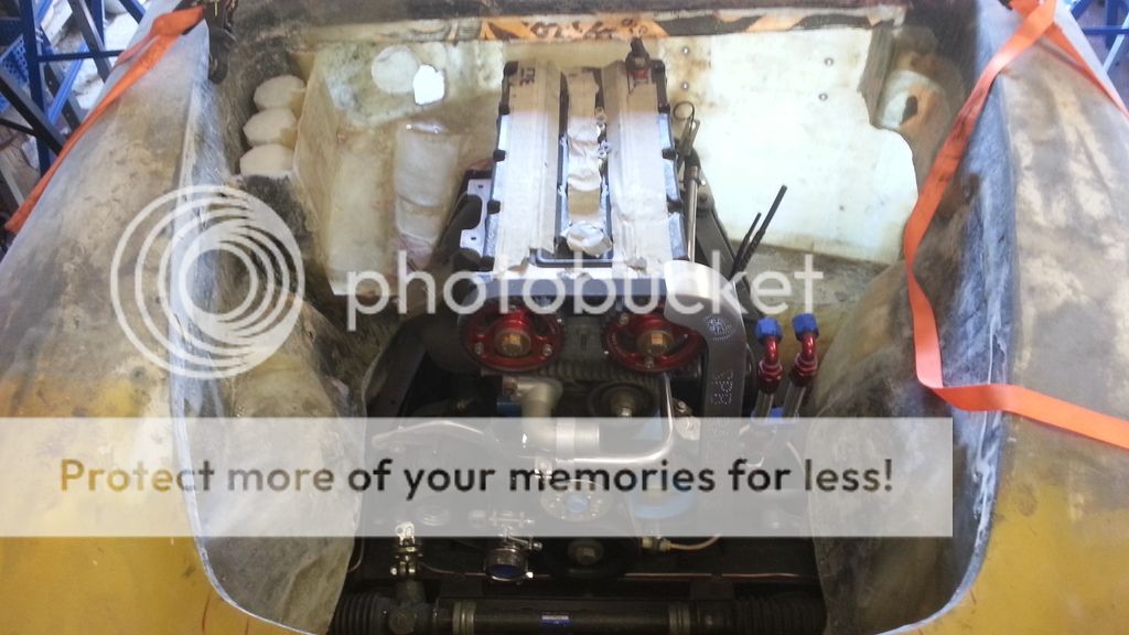


Finished the mods to the rad fan cowl. Weight saved - 500gms.


Painted the air reservoir:

 
I need to change one of the 90 degree vacuum hose connectors on the plenum for a straight one, but I can only find metal ones and these are 8gms heavier :)
 
Bought a new tool, lockwire twisting and cutting pliers. Once I figured out how it worked I did my first twist to secure the fuel regulator pressure pipe to the plenum. Easy peasy, should have bought one years ago.


IMO sadly twisted wire will look out of place given the exacting standard of workmanship on the rest of the Elan.:confused:

AN or push-lock fittings too heavy??
 
Last edited:
This is the standard way to do it until I can find a suitable alternative. And it is light :)

If you can point me towards a 1/4bsp thread 90 degree fitting that I can fit this 4mm ID pipe to I would be grateful.
 
I have used these on the gear change pneumatics (I have dozens of spares as it is cheaper to buy 5 from China than one from the UK). However, they are for hard pipes and aren't suitable for the race spec rubber vacuum/pressure pipe I am using. But keep looking please :)
 
I have been thinking about where to mount the gear change compressor. Decided that I could squeeze it onto the existing fuel system board, saving both space and weight.

All I needed to do was make some spacer brackets in order to clear the existing pipework:


Car is booked in for roll cage fabrication on 7 July. Yipee!

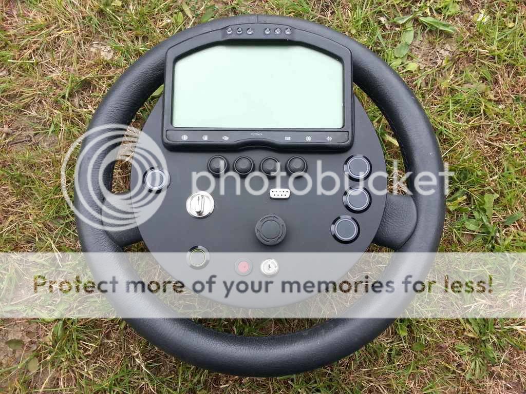
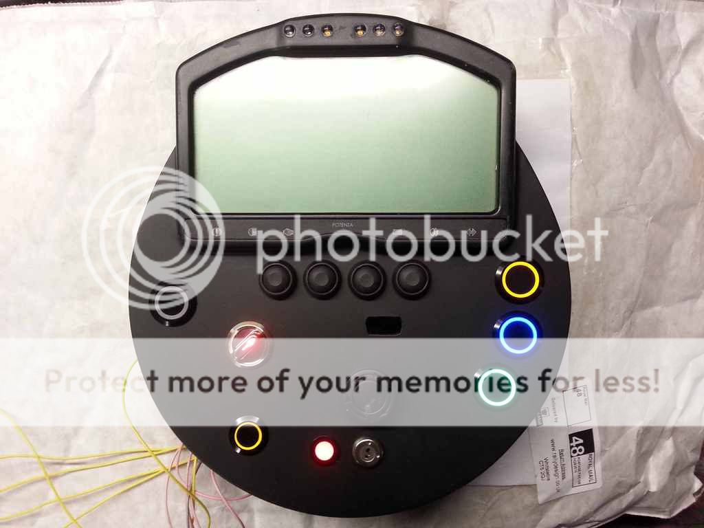
After many weeks faffing about with it, the steering wheel is finally finished, apart from wiring.


With the clock ticking re roll cage fabrication, I have got to get my arse in gear so will be working on the car every day until then. In order to keep me going I will be documenting everything I do on here, so I apologise in advance for this :)

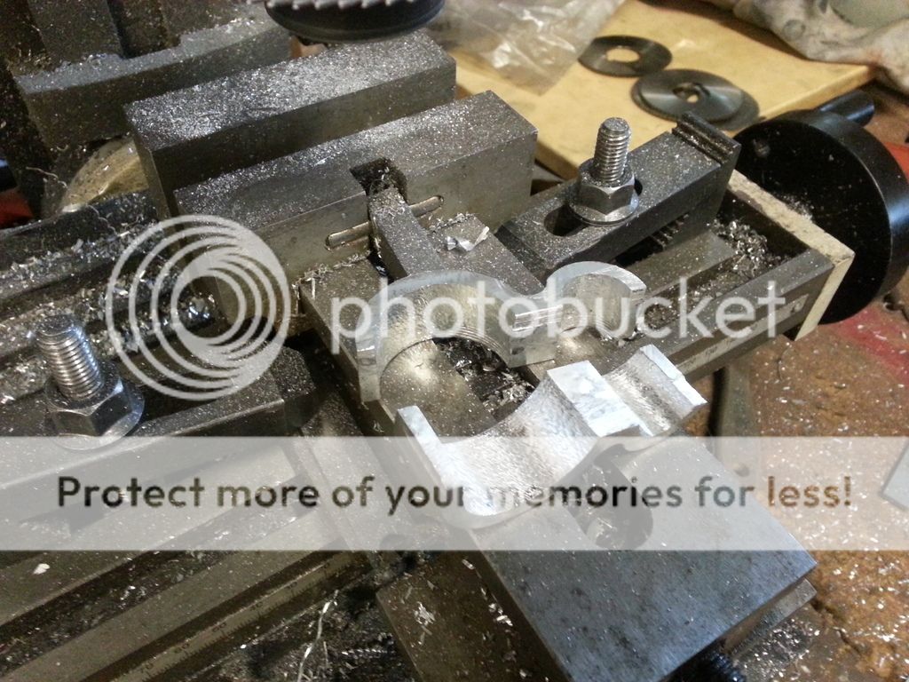
Today I spent the afternoon making a support/separator/bracket for the water pipe that feeds the oil heater. The spindle bearings in the CNC mill have developed some play so the cut finish is crap, requiring a lot of finishing :-( When the car is at the fabricators I will change them:


Not surprised the bearings are showing signs as mounting any milling bit in a 3 jaw chuck is bad practice ;) As an apprentice you only make that mistake once! Always use a collet mount in the spindle, less stress on the shaft and bearings plus you will get less chatter on the cut finish. Do you climb mill on the last pass? This will give an improved finish if only a couple of thou or even a pass back on the same cut.
 
The gear is great, the skill is so-so.
Not surprised the bearings are showing signs as mounting any milling bit in a 3 jaw chuck is bad practice ;) As an apprentice you only make that mistake once! Always use a collet mount in the spindle, less stress on the shaft and bearings plus you will get less chatter on the cut finish. Do you climb mill on the last pass? This will give an improved finish if only a couple of thou or even a pass back on the same cut.

Yes, I know :) The bearing damage was done by me constantly changing tool holders. I have a habit of over tighening the securing bolt so have to hit it hard to release the MT3 tool holder and this has damaged the bearings. This is a habit I need to address. The chuck was fitted as it is the only holder I have that can cope with the 19mm cutter I used for the steering wheel switch holes. I was lazy and didn't bother to change it to cut the clamp.

I was climb milling as this is the recommended method for CNC mills with ball lead screws (or so I have been told).

I keep looking at this, just need to justify the initial cost :)

http://www.coveng.co.uk/group/coven...lholders-for-manual-machines/easy-change.html
 
That set-up is ideal, money invested imo plus you won't be forever swapping arbors and having the already mentioned problems. I always climb milled when doing ends or faces. I tended to use end mills as you get a better finish but it depends on the depth of face being cut and if you can get a good size bit in where you are working. There's a lot of choices these days regarding cutters and design, nothing like when I was on the tools!
 
Although have all the gear (lathe, CNC mill, TIG, etc) it is sometimes quicker, and more fun, to get out the vice, hammer, hacksaw, drill, files and abrasive paper. I needed to make a bracket to support the turbo wastegate actuator as, as usual, there wasn't an off-the-shelf item available. An hour or so bashing, bending and grinding a couple of pieces of 1" x 1/8" mild steel and the job was done. I will need, however, to fit a heat shield between actuator and turbine.


I have had the turbo since engine was built 7 years ago. We have discussed various upgrades/mods etc but decided to just get the car going. It is a modified RS500 unit so no slouch :)
 
Well, we are getting there. I tack welded on the blind nuts that secure the gearbox mount to the chassis, my first TIG welds :)
It wasn't going at all well until I realised that I had it set on AC, which is for aluminium! Switched to DC and it was a lot better. Another 30 or so and I will have got the idea but these held and can't be seen :)


I had a phone call from my fabricator this afternoon asking for a big favour. His radiator job (around 20 of them) is taking longer than expected so could we postpone the roll cage until the 14th July. I made out that I was a little put out but agreed with good grace. Actually, this helps as I was beginning to panic. I can now take my time and it also gives me the chance to get my trailor up and running rather than having to borrow/hire one.
 
Due to the leverage involved and rigidity required, I thought it best to not weaken the brace. However, it was a close run thing :)
 
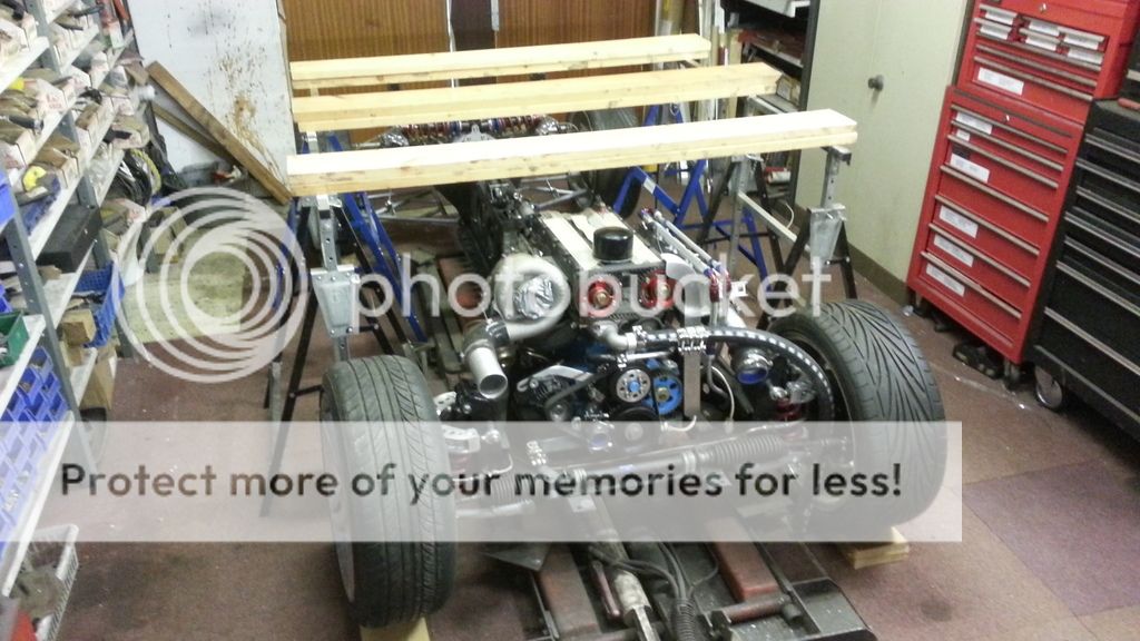
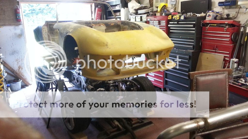
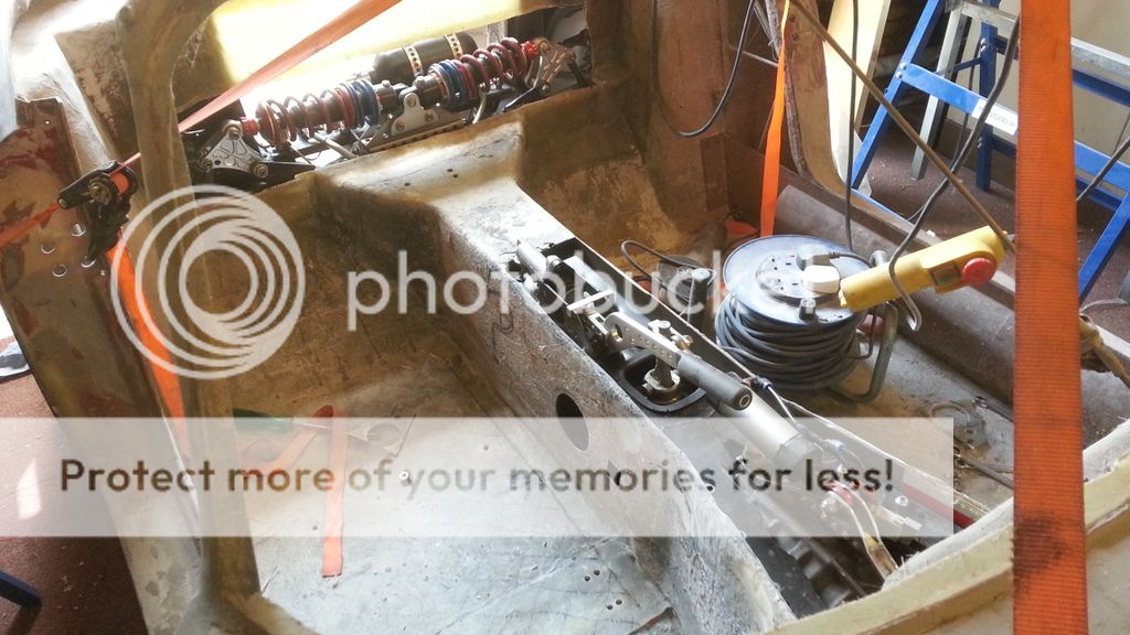
Body sitting over chassis. Tomorrow I will cut the holes so the body clears the rear suspension, pneumatics and hand brake. Hopefully it will then slide straight on :)


It looks to be on the slant, but that was just the photographer :)


The body, after a fair bit of chopping, is finally in place. Next job is to bolt it to the chassis then tidy up the openings. Once that is done I will get started on the covers for the holes. The one over the dampers will be easy, but the cover for the handbrake and gear lever/actuator will be a little tricky.


Similar threads


Please watch this on my YouTube channel & Subscribe.


Back
Top