Towards a two-stroke turbodiesel aero engine

malc9141

Torque Junkie
Points
70
Location
sheffield
Hi:

Under "How do you control an ECU?", I briefly explained what I'm aiming at.
It's all very difficult because I find I'm working alone. Therefore, if anyone wants to help in any way, please get intouch. I'm near Sheffield but distance isn't an insuperable problem.

Many years ago, I was one of those amateurs who built racing cars, and looking back, what we did, and even what we failed to do, gives hope for mankind. Then, everything was more flexible. I could drive in the early hours and have a CVC shaft made up by breakfast time at Hardy-Spicer in Brum, and have it fitted by the evening, with my day's work fitted in between. Bit harder now.

In the back of my mind, I wondered why the two-stroke was so neglected.
I now know why (control of combustion needed the advent of sophisticated high pressure diesel systems) but many of these problems/objections can now be overcome, so it should have a place. But, because of its smoke and particles, it is outlawed for land and sea use.

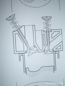
The other problem is, any poppet valve is used, the camshaft rate is twice that on a four stroke, meaning, say, running at 3000 rpm implies a pretty carefully developed valve train.

But its use for a propeller driven aero engine is ideal.
Do we need such engines? Answer, emphatically yes. Piston enginers are cheap compared to jets, and a propeller is reliable, with certain provisos.
Jet engines are incredibly costly, and simply hitting a flying bird may effectively write off the whole plane by cost.

Initial considerations

Propellers generate thrust according to diameter and revs. But if you increase either revs or diameter, you increase the tip speed of the blades. As they approach sonic levels, bad vibration occurs. So there is a fundamental limit. Whatever you do, you are limited.
That means restricting propeller revs, effectively.

You can get more absolute power by running the engine faster and using a reduction gearbox. Two probs: g/boxes are either notoriously unreliable, or heavy. Both bad. (I don't know why a simple epicyclic g/box wouldn't be OK. I think it would be). But the prop is like a huge flywheel and the g/box between it and the engine, and may suffer.

It would good to have low engine speeds with direct drive. But to get the required power, you need high piston pressure. The two stroke gives that each 360o rather than each 720o. Double the power.

What are we after?

Let's say we chose (about) 2500 rpm, let's say 2400 rpm for simplicity.
That's a nice prop speed to avoid sonic vibration, given typical prop sizes..
Now let's look at what flies at present.
The beautiful Diamond twin aircraft has two A-series Mercedes turbo-diesel four-stroke engines. They weigh about 140 kg and yield about 130 bhp. And they are far too underpowered. So let's say we aim for 240 bhp. Let's think ambitiously of a 3.5 L, 8 cylinder engine (there are reasons for this).

Each cylinder volume is ~450 cc, giving 30 bhp.

Mean Piston Pressure is Power/(Revs*Vol) because Vol is area (which dermines Force) * Stroke (which takes us to Work done).

So, in Watts, Revs per second, Pascals and Metres,
we get
Mean Pressure=1250000 Pa or 12.5 bar.

So that's what we are after with any model that is going to be scaleable to our purpose.

I need to build a single cylinder two- stroke turbo diesel that will provide 12.5 bar at 2500 rpm.

I'll post again in weeks to come, detailing progress.

If anyone wants to get involved in any way, I'll be glad of help,
as long as it's not a time waste.

Malc9141

(malcolm351@btinternet.com)
 
Chapter 2

I was lucky in making friends with a Senior Lecturer at Sheffield Hallam University. He had several good ideas. He suggested a Lister-Petter gutsy engine to work from, I had had some dealings with that firm and rang for advice. We learned we wanted an AC1 and an afternoon on eBay located one. This is a 6 hp diesel, floor mounted, to drive things like barges, or concrete mixers.
I proposed getting some 3rd year students to help with the project.
The engine cost about £100 but on dismanting, carried out by one of the students, it proved to have a cracked piston and scratched big-end bearings. Another £100 to replace those, but quickly done. The student then dropped out of the project, getting no support from the University Machine Workshops.
Meanwhile, I designed the layout of the new cylinder-head.
Another student modelled the gas-flow, using Computerised Fluid Dynamics (FLUENT program) and we learned of a problem, which was readily designed out.
This was a big leap forward and on discussing and searching, it seemed we might have something quite novel. Now, the chance of coming up with something new in Engine Design must be close to zero, so I phoned and chatted to a veteran of diesel engine know-how who worked in the Glasgow Lister-Petter agency where I got the spares from. He described something crudely on the same lines, but I couldn't even find reference to that on searching.

I'll talk about this concept in my next post. It's quite exciting and a patent search is in progress.

Meanwhile, there was a lot of serious time-wasting. The students went off to find employment, and our proposal to get a Masters project going fell apart. There were University officers who would talk, but when it came to doing anything, it was always manana (tomorrow). I realised I had been misled.

So the University and I parted company.

Then an ex-student came forward, signed on at Cranfield for a Masters Degree in Mech Eng, and who had his own workshop. He had plenty of ideas, but unbelievably, did nothing. Absolutely nothing. Surrounded by lathes, TIG welders, turret milling machines etc, he did nothing. Another 8 months went by, with promises being excused.

But I had found a machine shop in Sheffield which was willing to build the cylinder head. In the end, however, an order from, say, BMW would always push my job to the back of the queue, and I was lucky to get a block of aluminium squared off with a a few holes drilled at the right place. Nothing happened unless I went and stood there. Clearly, this was not going to be a goer.

The other people I found in Sheffield was a super Cylinder Head Repair firm, over in Wincobank. The boss was very enthusiastic and I learned details of where to source valves, guides etc. He said he should fit the valve seats, guides etc when the time came, but then he got too enthusiastic and wanted me to redesign everything. Where he was wrong, was in not keeping everything in his mind at the same time, so he wanted to take an easier path in one sense, overlooking the fact that it would cancel some other essential. He just wanted a diesel two-stroke. I wanted a certain power output. Twelve point five bar piston pressure, or bust.

Strange happening: a firm of ageing residual Master Cutlers outside Sheffield, open to visitors, proved to have a superb under-used workshop. "No, I could not use it, but perhaps a firm across town could help." They'd done a superb job making part of a huge candelabra for the city cathedral.
And there, finally, I met someone, half my age, highly intelligent, totally at home with his machine tools, who could usefully advance my ideas.

Next post:
The cylinder head design.

Malc
 
Chapter 3 - cylinder head design, general.

If anyone wants to throw mud at this, go ahead. If I'm an amateur, there's bound to be stuff I get wrong.

First, if we want lots of power, we will burn O2 and have heat to get rid of.

Back in the "old days", English formula 1 engineers built engines with "large pots" and fewer cylinders because it "gave a simple rugged design." The opposition built multi-cylinder engines. Guess which engines burned valves out.

If we think of an individual cylinder, its volume (roughly) predicts the amount of air in it to burn. So for given revs, volume is proportional to heat generated (power). If we halve the volume, we get half the heat (power). But the combined area of the cylinder walls, piston top, and head-face are not halved. Volume is L^3, area L^2. So the heat "seen" by the walls is less, per unit area. Now heat isn't exactly temperature but it's proprtional to it. So I argue that a smaller cylinder is safer than a larger one. But you have half the power, so you need twice as many cylinders.
Remember, for an aero engine, reliabilty is paramount and overheating or burning exhaust valve seats must be designed out at the beginning.
Common experience tells us what a reasonable cylinder size is, but aircraft engineers are historically accepting of big pots, and petrol engine failures are all too common. (It's interesting how such failures always seem to be explained away as "fuel contamination" or "poor maintenance").

So about 450 cc for a pot seems right. For reasons I'll discuss later, for a turbo engine, we want an under-square configuration. In any case, we can't go for high revs.

That means a bore of, let's say, 80mm.
The most robust design is the Heron head, but since a two-stroke has almost total overlap of valve opening, the incoming air goes straight out of the exhaust. Worse, the stream of air actually impedes the residual exhaust gas from exiting.
What we want is: the standard explosive exit of exhaust gas, with if possible, the well known temporary vacuum created behind its momentum. The inlet valve opens at this point (of course, openings are not instantaneous) and the turbo-pressured air comes in. I argue that we want as smooth an entry as possible with minimum turbulence. (Turbulence is for the birds, and carburettors). We want the air to be as slow and smooth as we can get it (given we have about 7 milliseconds to get it in!). We do not want jets of high speed air. Why? Jets cause a local pressure drop and absorb the surrounding gas (exhaust fumes). It looks good, seeing high speed streams of air but it ends as a high volume, low velocity mixture of diluted oxygen. We want the air to come in like water, and expel the residual burnt gas as if it's oil. And then the exhaust valve closes.
To do this, we have to design a particular shape of intake port. This we did, and built a scale model with a glass partition, which showed the flow patterns when we pumped through high velocity air. We used children's fireworks sparklers to show the flow, and b/w photography to confirm the validity of the design.
I can't show the exact layout because it's the subject of a patent application, but it is simple and robust.
The nice thing is, the water cooling can be concentrated on the exhaust ports, and air cooling we believe will take care of the combustion chamber region. But above all, there is a low total surface area, meaning that heat stress in the head is minimised. (This is not at odds with my remark in para 4. That's heat per unit area, this is total heat pick-up).)
So we have a head with a simple surface, the combustion chamber under the cool inlet valves, and an air-flow pattern that scavenges well (perfectly?). We have done away with the usual inlet ports in the cylinder liner (jets, and bad ones at that), and have a smaller piston (no lomger doubling as a sleeve valve), lowering the whole engine, making it stiffer and lighter.

Next: Building the prototype head.

If anyone wants to get involved with is project, let me know.

Malc9141
 
Chapter 4, April 08

A lot of time taken up trying to get the hang of the ultra-high pressure injection control. Plodding on.

Meanwhile, here's some updating of the cylinder head. A diagram of the layout looks simple, and it is. I believe that's the beauty of it.

url='http://www.torquecars.com/forums/vbimghost.php?do=displayimg&imgid=53']
thum_29854808cba7633cb.jpg
[/url]

It's an oversimplified drawing. But remember in a two-stroke both inlet & exhaust overlap hugely. So clean air tends to go up the exhaust spout (note Z). Here, by creating a barrier to airflow towards the exhaust, spent gas is pushed out first. (Don't mention exhaust tuning - impractical in an aeroplane).

But (I hear you say) there's a barrier to a portion of the air trying to get in. True, there has to be (note Z), and does air flow mainly to the side opposite the exhaust, but also out at the side of the valves - and also, not shown - there's a clam shaped bleed (expanding air slightly) on the central side of the inlet valve, letting air go straight down.
So plenty air gets in but shouldn't mix with the exhaust. It should force the spent gas out.

To test this, I made a scale model in wood. It isn't as crude as it looks - the plasticine seals blunt the image. The flow is shown by sparks (which aren't quite like air, but make a good foto). Sparks bounce around. When I sift flour in, the flow is seen beautifully but it doesn't foto well.

You'll notice there's a stagnant zone under the inlet valve head. With modification with plasticine, I could show that seeds, stuck on pins with butter, were whisked off. So there is airflow under the inlet valve also. Other mods didn't help much.
Keep it simple.


In the picture, the shovel pushing sparks rightwards is the inlet valve and the tract on the left is the exhaust. The horizontal "barrier" is the ex valve head. All shapes were profiled, tho' the picture doesn't show this. The bottom is the piston top, and a small ramp on this was helpful.

As I get the hang of adding fotos, I'll give some pictures of the head being machined in stages.

Malc :)
 
22 April 08

I'm spending a lot of time trying to get the hang of controlling the injection. I think it's going to be possible.

I show here the prototype cylinder head. It was machined from solid alum alloy. Four valves, with machined tracts. The cylinder size is 325cc and the inlet valves are 29mm od the exhaust 25mm.
The springs were from a Yamaha - and I'm just going to use the (smaller) inside one of the two springs per valve. (The Yammie motor revs to God-knows-what so the dual springs are very very stiff to stop bounce).

When the valve closes, if it slams against the seat, that's bad for the seat, so I think a minor preload is OK. Which is what I've got. The inlet valves are from a VW 20-valve engine, exhausts from a Fiat of some sort. It's a case of needing certain valve stem lengths to suit the angle of the tract + then spring length has to be fitted to suit.

Camshaft - I'll do that next time.

The inlet and exhaust tracts can be seen. The larger inlets (second foto) drop straight down from on top - the two holes on top are the where the inlet manifold will fit. The exhaust holes are at a 40 degree angle so are oval - their manifold would fit into these exit holes.


To MALC9141 - why are you trying re-invent the round wheel.

That round wheel of which the Greeks and Romans were eminently proud?

I, for one, am not willing to take a craft airbourne powered by a single cylinder engine.

Whether or not it's fuelled with diesel, petrol, corn oil or potato peelings. One cylinder is not enough.

I wish you luck with your ambitious project; I think you're on a hiding to nowhere; and I think that it won't work.

Having said that, I hope that it does come to fruition,

Kind regards,

Paul Anderson.
 
One cylinder is not enough.

Ha Ha. I wouldn't fly in a plane with a 1950s petrol engine, either. Like your average Lycoming.

Actually, I've written earlier on these posts quite a lot about the concept. I personally couldn't build a aircraft engine. I doubt if anyone after, what? - 1910 - could.

An aircraft engine should be designed just for that purpose - not a modified car engine.
There is a three cylinder engine which is not bad but I would like to see a V6 or V8. About 3 L capacity. But to build anything like that is beyond anyone other than an established manufacturer.

No, I wanted to convince a particular manufacturer that a certain design would have advantages that seem to have been overlooked. Central to this "proof of concept" is the inlet valve arrangement (which in my foto does not show final machining but never mind - - later) and gas flow. But there are six other advantages that follow and no disadvantages.

I can test the effectiveness of the idea (prove or disprove - I can't predict if that will work) best with an uncomplicated single cylinder engine. If the idea is right, then I can argue that "this is the way forward." (I doubt if anyone will listen which is the way of the world). But there is a manufacturer - & I know those guys well enough that they just might be interested.

But do you know, it cost Diamond/Centurion nearly a million Euros just dealing with the EU Regulators - proving that their motor is ultra reliable. Not manufacturing - proving it was safe. If it breaks down, the AA is a long way off!

So, no, I'm not building an engine to fly a plane. I'm building an engine which - if it does what I hope - will allow an aero engine to be designed using this concept.

All ze best

Malc
 
Rather than a dual acting piston, how about have two pistons directly opposed in the same bore with a central injector. A bit like a single cylinder from one of the Deltic units of Napier fame. British Rail made good use of these in the Class 55's.

These had two eighteen cylinder (thirty-six) piston engines on a common crankshaft with the generator in the middle.

72 pistons - on a two stroke.

http://rowla.dyndns.org/justin/img/piston_deltic320.mpg
 
To HDi: someone did build a prototype piston engine as you suggest in the 1990s. It would have been quite heavy. It never got off the test bench but that doesn't mean it would be no good. But it must be able to meet the skeptics' views if it's to get Certificated. ;)

But what you need for an aero engine in the apparently conflicting requirements of simplicity and sophistication. Simplicity for reliability and costs and weight, sophistication for economic high performance. I think my design - if applied to a multicylinder engine would fit that mould. :p

To Wayne: I don't know about a Rotary. Interesting idea. Propellers are liable to break with vibration and a rotary would get round that, they're smooth. (My multi cylinder concept - nothing new in more than one cylinder!!! - would be pretty smooth, esp being 2-stroke).
A rotary with modern smooth burning diesel injection technology might work quite nicely.

Malc :blink:
 
To Malc - if vibration is a problem then diesel is not the way to go. Diesel cars use a multitude of devices to minimise vibration. Diesels are generally heavier than petrols. And more complex.
 
Well, vibration is relative. The Wilksch 3 cylinder is fine (see www.wilksch.com). But the Renault 4 stroke (car motor put in a plane) was too troublesome. The Centurion is a Merc A series 4 stroke and is OK (just).
A two stroke is smoother, each burn is less explosive than in a 4 stroke ('cos you've only got part of the revolution to do it) but there are twice as many. It's smoother - it's good.
That's why I follow this path. But you're right, you gotta be on the watch.

Malc (What's the diesel related idea??????)
 
Actually, now I remember, Mitsubishi spent squillions across the turn of the century on a rotary diesel for light aircraft and eventually gave up. Not sure what the problem was. They used another name for the company (so it didn't seem like a Mitsubishi failing).
Maybe it wouldn't run lean, don't know. Nice idea though.
Malc

They laughed at Eccles
 
As an aside! Can you theoretically do a rotary diesel engine?

There are certainly diesel powered turbine engines in service daily - they differ little from aircraft jet engines. Jet fuel is broadly similar to diesel, too. Turbines are probably the most perfect rotary engines. Effectively an infinite number of cylinders - hence the phrase 'turbine smooth'.

I'm not sure if you can do a Mazda type of rotary because the injection ports are obscured by the rotor tips at full compression so there's no way to get the fuel in at that time which is what's required by a diesel type engine.

NSU was the innovator behind the Wan*el engine in the 1960's. IIRC, Audi grew out of NSU.
 
Last edited:
It was Wnkl rotary engine Mitsubishi was trying to do, unsuccessfully, maybe to do with the reasons you mention.

Jet turbines are beautiful but very costly. There are small aircraft effectively written off cos a sea-gull writes off a jet engine, and replacement cost exceeds value of having the plane earn a living.

(Things here are at a standstill again. It's like treading water).

Malc
 
As an aside! Can you theoretically do a rotary diesel engine?

no a rotary engine wouldn't be able to do it because the compression wouldn't be high enough and it's key on a diesel engine

plus the rotary engine is known to be free revving and diesel works better at lower engine speeds....
 
I agree. I wonder what it was Mitsubishi was trying? Maybe they thought with a supercharger they could make it work. Anyway, it didn't.

I'm slugging on. Building the valve gear. This is the clumsiest part, because the engine I've adapted doesn't give easy access to its camshaft.

I'm also plugging on with the electronics, which I'm unhappy about because "I feel it's unfair" that I'm having to tackle this problem outside of my knowledge base.

But it's cheap to experiment. One insight, tho' it's only my own idea:
If you cut a current in a coil, you induce an EMF. We all know that. So when we switch off the solenoid (which controls the valve which controls the piston which controls the pintle, and the partridge in the pear tree), we get a high voltage. That is fed back to the capacitor, one-way ticket - simple diode - and THAT is where the high voltage in the capacitor comes from, for the next opening. It's brilliant. I couldn't understand how a high voltage (say 30) appeared with a 12 volt system. I assumed there must be a (I can't remember the name) special voltage booster. But I don't think you need one.

Finally, I am trying to design a simple way of switching, using the flywheel. Present idea, a reflective patch on the f/w and a an infra-red diode and a receptor hung over it. So far, I have not managed to make the circuit work the way I want. But I can't see anything wrong in principle.

Fool on.

Malc
 
Capacitors aren't diodes.

What's the ultimate goal Malc?

Reciprocating diesel cycle engines have been employed over the years for countless duties. Railway, road haulage, recently they've become very pleasant to drive in swift passenger cars.

BR's class 55 was an object in point - two stroke diesel. Fast revving and lightweight.

But is a compression ignition engine likely to compete weight for weight with a petrol aero engine.

I'm not saying not ever, just maybe not now.
 
I would never mix up a capacitor with a diode!
The diode allows the current to flow one way to the capacitor, but not back again.

As for the purpose of the project, I wrote about this in detail at the earlier stages.

The problem with the English, if I may say, is that they always look for reasons for NOT doing something. You get it all the time. That's why from the huge motor industry in the 1950s, we now have zilch home-grown. Any initiative left over goes into the relatively small (on a world scale) motor racing industry.

Because of its efficiency, and therefore lesser fuel weight in the tanks, diesels will be used in light aircraft.

I'm not trying to pretend I have stumbled on compression ignition. I earlier said, The British invention, the tank, which actually won the First World War, was powered by a two stroke diesel. Of course there are the Delta engines etc, but if they're so good, why aren't they still being used? Ditto the truck engines of the 1950s. But I do think I have a design which is superior to earlier two-stroke diesels.

If my combustion works as I hope, it will allow a lighter engine than anything before, using a lighter fuel load. Ideal for a plane. Vibration? A worry, I accept, but the 2 stroke is less efficient per burn than a four stroke and there's less "hammer." But you get twice as many per rev. Ergo, smoother.

It is great to have encouragement and your tone is always that. Thanks.

Malc
 
Hi there

The modified Merc engine is too heavy. The Renault maybe same.

The Wilksch engine, a two stroke designed specifically for light aircraft, is OK weight-wise. (It's design weakness lies elsewhere).

So I think it can be done. (The wilksch engine uses alloy but clamps head to big-end caps with steel rods). If my idea works, one of its properties is that it will be less high, less tall, than a typical 2-stroke, so I can beef up where needed without worrying about weight (Of course, I would consider weight all the time but I'd have something in reserve).

How is it smaller? It's the head design, again. It will allow a smaller piston height. More like a four-stroke piston than a two-stroke piston. So I save 30 - 40 mm on the overall height. Ditto con-rod length. Not sure how much weight is saved but you can see it's in the right direction.

But I'm miles away from that. I haven't proved the head will work!

Fool on

Malc
 
What about ignoring DERV as a fuel and considering a compression ignition enigne that's fuelled by petrol (gasoline, for the American readers). You won't need the enormous compression ratios that are required to set light to diesel. So, perhaps a lighter engine.

It would still be a diesel engine, by which I mean compression of air alone is the source of ignition, but using a high distillation fuel (petrol ish) instead of heavy oil.
 
Yeah, it's a thought. My idea was to use Jet A-1 same as turbojet engines use because iof its availability. It is a bit lighter and there are more double bonds giving more calories.

The problem is, Chris, I've got so much on my plate that it's difficult to experiment. At this stage, if I can get it to tick over, I'll be pleased. And if it won't, I did wonder about using petrol since I'm starting from scratch, so to speak.

Ther have been lots of radical ideas - do you know the Saritch engine? It's a long way from just using a different fuel, but it was supposed to change the world. Curiously, I think after giving up, they've turned to developing small 2 stroke diesels, so I may be in for a shock!

Anyway, every now and then, the thought of an outsider waters a little seed.

Malc
:rolleyes:
 
Quote: "do you know the Saritch engine?"

I don't know this engine at all but I'm about to do some research. I'm still in aircraft engine mode on account of this dialogue despite my almost non-existent knowlege of aero engines.

As such, please answer me a question. If we took a single engine (prop, pilot only) plane, what is the typical peak power of the engine? It's a very vague question, and I'm looking to you for further information. Basically, how much power is needed to get a certain mass airborne?

I know that there are 50 million other considerations and criteria but I'm just trying to get a very blunt figure in my mind to which I can apply the ever more depleted grey matter.
 
HDi the grob tutor planes that are/ were used by th RAF to train in ( iknow the cadets and universaty air squadrons still use them ) are powered by a 2.5 flat 6. think it only develops 150ish bhp but will double check in a couple of weeks.

the grob is a 2 seater prop driven not sure about the weight thou
 
Power :embarrest:
A two seater sports plane works well with:

the Austrian petrol ? engine, about 85 bhp.
The modified A series Merc engine (Thielert), now causing trouble (weight, unreliabilty), is 135 bhp.
The Wilksch engine aimed for 120 but gives about 105 bhp.

In Light Aircraft, eg 4 seater, you need about 200 bhp. At present, that is typically with a 50 year old design - the Lycoming.
Etc

Q. Why so little? More would give faster take-off among other things.
A. Power is (aw we all know) revs X torque. Propellers can only rev up to about 2500 in a real plane (a tiny model is different) so low revs hold down power. :confused: Torque is what is needed.

Why not use a gearbox and rev faster? You can but the g/b is heavy, stuck right at the front, and notoriously unreliable :sad2:.

Why unreliable? I don't know but they give trouble.

Malc :amuse:
 
If we're talking about open prop aircraft at this point then there is a theoretical maximum tangential velocity of the propellor tips. Without considering all other balance issues, we don't want the prop tips to be moving at supersonic velocities.

So, what kind of aircraft design do you have in mind? Most single engine (and lots of twin engine) use directly coupled props without any gearing. As you say, weight is a big issue. Can a diesel principle engine run high enough RPM's to run a prop directly?

This is not a typical British 'won't do' - more a how can we do kind of thing?

Regards,

Paul.
 
Right on.

I know a turbo prop is geared down to about 1700 rpm. That's quite a big prop in, say, a 30 seater plane.

In a light aircraft (defined as < 8 persons + pilot), I'm not sure. I think the power they need defines a prop at about 2500 rpm but I'm open to argument. I talked to Diamond about their Twin engined plane and 2500 rpm was seen as absolutely fine.

In a Ultra-Light (not Micro-Light), defined as <800 kg wt at take-off, the Rotax (I think) runs a prop at 300 rpm. In the Wilksch prototype, the prop (3 blade) runs at 2750 rpm.

So there is some lee way. It's just that, as you say, you can't ignore the question of tip speed. (I just wonder how those famous Spitfires got nearly sonic in a dive. Hard to believe).

I'm aiming for 2500 which I know is OK for a 250 bhp engine, because I've discussed it with a German Prop maker in detail.

(Vibration is the only concern and I'm hoping that a multi-cylinder 2 stroke would be more free of vibration than a 4 stroke: less efficient burn, but twice as often).

And I am light years away from that stage. I haven't even got the single cylinder test engine built.

Malc, who values the discussion which is good for moral!!!
 
Can a diesel principle engine run high enough RPM's to run a prop directly?

Yes, this bit is fine. 2000 to 3000 is OK. It's all due to modern fuel injection - tho' having said that, the Wilksch engine is old one-squirt mechanical FI into a side chamber. But it ran at 2750, now de-rated to 2500 (heavy piston, precisely one of the things I'm intending to avoid)
As you've said before, vibration is a worry, and that's what the four stroke diesels have found (Mercedes and Renault).

I am hoping (and I may fail here) that a two stroke will have smaller, higher frequency vibes. But the Wilksch 2 stroke is very nice, I've flown in it and it's smoother than any petrol Lycoming I've been in. (Tho' one is 2 litres, blat-blat-blat, and the other about 5 litres, bang, pause, bang):D:eek::confused:

Malc
 

So, what kind of aircraft design do you have in mind?


As I've said above, I'm not even out of the starting gate yet. But I would like a 3 litre V8 for the Diamond series airframe (see www. diamond.com.at)

Cheese
Malc
 
If you work it out, you'll see that asking 250 bhp from a 3L is quite ambitious. If you factor in 2500 rpm.

For "my" 2 stroke, that's a mean piston pressure of 12.5 bar. That's achievable because of the turbo charging, but it's still ambitious.

:amazed:
Malc
 
Update on progress.

I'll stick to the Fuel injection, for now.

When I was involved with the Wilksch diesel aero engine project, its engineers were in awe of modern high pressure DFI. I asked, Why not use it? And got silence in reply.

So I didn't think I'd be able to tackle the DFI and badly needed someone to take this on. In the early stages (2006) there were folks whom my associates knew who'd be able to do this. Of course, they weren't there when I asked.

So I've had to do it. Some learning curve :confused:. HDi has had some input here (thanks). A friend managed to get the relatively unavailable Bosch book, and send me some vital photocopies.

I reluctantly worked out an electronic circuit and it was met with derision by anyone who saw it. Ironically, something very similar is now being suggested by an expert - which ain't surprising, seeing I was trying to imitate the Bosch design, without all the bells and whistles.

Anyway, a man, now a valued friend, used a different approach.He worked out the values for the parts - some capacitors, many resistors + some Integrated Circuits.

What I built (Note: I am not keen on electronics, but I had to convert a circuit into board that was reasonably tidy. It gave me a headache and I don't often get headaches!) was - using his plan:

A device to supply current (at 12v) that would open the solenoid in the Delphi injector. Current comes in over 200 millionths of a second (200 microsecs). At a current (adjustable) between 8 and 16 amp.

It immediately switches itself off, because a second Current Generator has also come in at (adjustable) between 4 and 8 amp (12v). This can be held in operation for between 0.5 and 2.5 millisecs.

These are the sorts of time the injector injects for :blink:!

These current generators are switched with each of two parts of an Integrated Circuit (4013). This circuit is in turn activated by a very short pulse from another IC, which gets its pulse from the flywheel. The flywheel has a little shiny bit of stainless steel which reflects an infra-red ray to a diode and triggers the initial pulse.

Just to cover all bases, we have a second infra-red switch, with different flywheel timing, which links to Current Generator 1, to give an extra quick squirt if we need one, either before or after (or both) the main squirt - eg a late squirt for a late burn for the extra O2 thanks to the turbocharger.

It works on the bench but the engine itself is still in progress so its real effectiveness is unknown.

To summarise: two separate bursts of current, the first large to get a very quick response, the second burst being a holding current, control the injection.

A final point: we really need a 60 v system (and can adapt to that) but we sense that this 12 v will be OK at least to get started. Why 60 V ? Obviously a higher voltage will force the current in faster, against the Back-EMF that any coil generates.

Next time, I'll briefly discuss the High Pressure fuel pump.

After that, I'll fill in on progress with the motor. The cylinder head is beautiful (wanna see a pic?) and so..oo..ooo tightly packaged, but we're trying to get exhausts and inlet pipes built and getting the old run-around again.

And after that, the Dynamometer. (I would never in a million years imagined I'd have build my own Dyno, but I am).

I sense success. I need a qualified engineer for the stage beyond this. Anyone out there?

Malc
 
Hi Malc - starting to see light at the end of the tunnel. I must congratulate you on what you have achieved so far.

I'd love to see pics of the cylinder head.

I reckon you should build a second back up engine in parallel just in case the worst happens.
 
I'll get the picture of the head soonish.

I've decided to do the exhaust outlet myself. I have two parallel ports coming out of the head. They emerge pointing up at 40 degrees. So to level them off for a horizontal turbo charger, need two bent pipes.

I got these, a mere £27, (holidays in the Bahamas?) and will now weld them into a siamesed pipe.

I am lucky because my friend said, "Mill them down, and weld them together." So I will.

I have to calculate what angle to hold them, to mill them and how much. It's simple geometry and another little piece of fun (easier than the endless dead ends I had trying to work out the circuitry for the injectors. I thought Henry was the guy next door, and microHenry his offspring, but it turned out to be vital for the injector solenoid!)).

Back to the exhausts: I know how far apart the pipes are as they come out. Also, the cross-sectional area (which must not decrease), and the circumference of the pipes. So I can work out how much to machine off, and at what angle. Then I weld them side by side, and belt the oval hole into a circle to meet the turbo manifold.

That's the good news. Bad news, We're out of Argon. Will this thing EVER see the light of day????.

Malc:sad2:


Similar threads

Similar threads


Please watch this on my YouTube channel & Subscribe.


Back
Top