At Last!. I have started on my car ;-) PART 2

My sister-in-law arrived from LA today with more bits for the Elan.

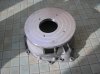
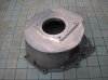
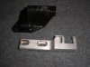
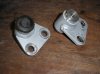
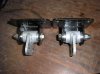
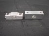
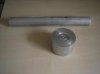
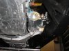
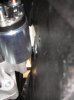
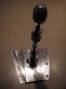
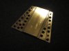
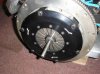
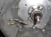
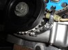
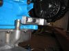
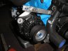
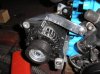
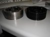
Lightened CV joints, 172.5gm lighter than standard. They have 4130 chromoly cages and hardened inner/outer races.

This saves 690 grammes of rotating mass. (which is equivalent to the performance improvement of removing approx 6Kg from the car's non-rotating mass).

Bringing them over from the States saved me approx £100.

I can now sell my unused standard joints.


http://www.torquecars.com/forums/attachment.php?attachmentid=1105&stc=1&d=1306874133
 

Attachments

  • elan cv joints (1).jpg
    elan cv joints (1).jpg
    22.8 KB · Views: 8
Last edited:
Just got the bellhousing back from my friend's machine shop. He has been attacking the large lump of aluminium welded to the end of my bellhousing where it has been shortened. He removed just over 1.5Kg. This is a reduction in excessive weight rather than a lightening as it really shouldn't have been there in the first place.

http://www.torquecars.com/forums/attachment.php?attachmentid=1109&stc=1&d=1307558655

http://www.torquecars.com/forums/attachment.php?attachmentid=1110&stc=1&d=1307558687
 

Attachments

  • elite bellhousing.jpg
    elite bellhousing.jpg
    38.3 KB · Views: 8
  • bellhousing lightened 08052011.jpg
    bellhousing lightened 08052011.jpg
    34.7 KB · Views: 7
I have no idea. The original car weighed 700Kg. The Cosworth engine weighs approx 46Kg more than the original twin cam and the diff and drivetrain are also a lot heavier. Against that, I have removed the heater and radio :)

I have also reduced weight by using CF doors (with plastic windows), boot, bonnet, dash and seats. Lightweight calipers, alloy hubs, titanium wheel nuts, etc, etc, etc. I hope to keep it below 650Kg but would like to see it down to less than 600. Once the CF body is made we should be close to 500Kg.
 
wow og 2151 views on Part 2, This is probably our most popular thread to date!

Nice to see the progress.
 
Well, it's nice to know that people are interested in the car. I just hope it lives up to its promise when it finally runs in anger. What it won't be is overweight :)
 
Well, it's nice to know that people are interested in the car. I just hope it lives up to its promise when it finally runs in anger. What it won't be is overweight :)

I am sure that fantastic car of yours will live up to everybody's expectations OG :)
but if it does not! Hang your head in shame get your coat then turn and walk away! :lol:
 

Attachments

  • rear arb brackets.jpg
    rear arb brackets.jpg
    40.6 KB · Views: 6
This bracket supports the rear of the diff. However, with 6 other bolts fixing the diff rigidly to the chassis, it doesn't do a lot of work so a little lightening was in order. So far, with a few more holes still to drill, 200gms have been removed.

http://www.torquecars.com/forums/attachment.php?attachmentid=1120&stc=1&d=1308519798

I use AVG virus software (freeware) but they have an offer on at the moment where, if you buy something from selected companies, you get the retail version for free. So I bought some free cards (only pay for postage) from Vista Print for a giggle. As I didn't use the custom options (which cost) they are pretty basic. When we have our cars up and running we will get proper cards made with all four cars on them :)

http://www.torquecars.com/forums/attachment.php?attachmentid=1119&stc=1&d=1308519561
 

Attachments

  • 997 club card.jpg
    997 club card.jpg
    28.1 KB · Views: 5
  • diff support bracket.jpg
    diff support bracket.jpg
    25.8 KB · Views: 5
Last edited:
Latest project.

The sequential box I am fitting has the gear lever at the end of the box which puts it behind me in the car! I have to, therefore, install a remote lever.

Elite can sell me another lever, but want £200 for it so I have decided to make one. The raw material is shown below (cost £5) and I will add a photo of the finished article in due course.

http://www.torquecars.com/forums/attachment.php?attachmentid=1133&stc=1&d=1308867227

Prpgress report - Spent all day Saturday playing and got as far as this :)

There is a roller bearing fittied in the lever that the bolt passes through. There will also be VERY narrow roller bearings between the lever and housing.

The large lump on the end will be removed and the original knob from the Elite box wil be tranferred to the new lever.

http://www.torquecars.com/forums/attachment.php?attachmentid=1134&stc=1&d=1309038794
 

Attachments

  • gearbox lever blanks.jpg
    gearbox lever blanks.jpg
    18.4 KB · Views: 6
  • gear lever part made.jpg
    gear lever part made.jpg
    20.8 KB · Views: 5
Last edited:
Gearlever almost finished. Managed to break the nylon high/low gears in the milling machine so awaiting replacements from China.

http://www.torquecars.com/forums/attachment.php?attachmentid=1144&stc=1&d=1311029840

The flat plate has yet to be machined to accept the gear lever base. Bolts will be recessed into plate.

http://www.torquecars.com/forums/attachment.php?attachmentid=1145&stc=1&d=1311030132


Finailly found a starter motor that fits without fouling the chassis (still needed a little adjstment with a slidehammer).

http://www.torquecars.com/forums/attachment.php?attachmentid=1146&stc=1&d=1311030132

http://www.torquecars.com/forums/attachment.php?attachmentid=1147&stc=1&d=1311030132
 

Attachments

  • gear lver fabrication 17-07-2011 (1).jpg
    gear lver fabrication 17-07-2011 (1).jpg
    67.5 KB · Views: 9
  • gear lver fabrication 17-07-2011.jpg
    gear lver fabrication 17-07-2011.jpg
    39.1 KB · Views: 11
  • starter motor fits (1).jpg
    starter motor fits (1).jpg
    40.4 KB · Views: 12
  • starter motor fits.jpg
    starter motor fits.jpg
    18.1 KB · Views: 9
Hey Steve,

I've spent the past few evenings reading the two threads you've created to cover this build. I must say that it's definitely one of the most detail orientated builds I've seen in a while. Excellent fabrication skills and a job well done thus far! Something you should be really proud of.

I look forward to seeing it completed. Keep the posts coming.

__________________
Nick M.

A journey in design and fabrication begins with a vision, a single pen stroke ... and in some cases the blow of a hammer.

Some projects: http://www.facebook.com/iNVisionPrototypes
 
Thanks.

Project is taking a lot longer than originally planned, but what project sticks to a timetable?

It is moving forward but there have been quite few periods of inactivity over the last couple of years. However, I am seeing regular progress now so am still hopeful to be out next season.
 
An ordinary mechanic would have had it done by now! But a craftsman always takes just that little bit longer OG ;)
 
I am jealous, wish I had the room for a couple of small machines, would make my projects more interesting and looking as good as yours. It is times like this that I miss working on the tools and having access to everything I need. When I was racing I was always machining things up, modifying and weight saving. Nothing better than creating something that any raceprep workshop would fit to their cars. Alas I do think as a project such as this is never finished as you will always strive for perfection and improvements. Excellent work.
 
I need some feedback on my flywheel conundrum.

My engine is fitted with a flywheel weighing in at 8.6Kg. A lightweight replacement can be down to approx 4Kg. Although that is a lot of rotating mass removed I am concerned about the effect on standing starts. A heavy flywheel helps to stop the engine bogging down in a normal car that weighs over a tonne. However, mine will weigh almost half that and with 450lb/ft I contend that a heavy flywheel isn't so important on my vehicle and the saving in rotational mass is significant. In sheer weight (sorry HD, Mass) alone it is equivalent to 4bhp/tonne.

Any racers out there got any thoughts or advice?
 
Just in case people were beginning to think that this project had, like many others, died :)

Finished remote gearlever bracket this evening. Doesn't need to have a car show finish as it will be hidden. Lump of aluminium originallyweighed 1200gms but it is now down to 470gms. Every little helps ;)

http://www.torquecars.com/forums/attachment.php?attachmentid=1355&stc=1&d=1326672806

Also fitted pipe bulkhead fittings to bellhousing so clutch pipes can be fitted.
 

Attachments

  • elan remote gear lever.jpg
    elan remote gear lever.jpg
    13.7 KB · Views: 14
Last edited:
I tried that kind of weight shaving off her indoors! Once the doctors assessed my situation after her assault and chatted about it for a week or so, they decided they could sew it back on without any loss off feeling :lol::lol:
 
Update

Today -
Made and fitted clutch pipes from slave cylinder to bellhousing.

Fitted clutch

Started to make crank sensor bracket as original doesn't hold the sensor in the right place due to a change of pulley design.

Dry fitted remote gearlever support. Final position of lever won't be decided until body and seat are fitted.

http://www.torquecars.com/forums/attachment.php?attachmentid=1368&stc=1&d=1327103104

http://www.torquecars.com/forums/attachment.php?attachmentid=1367&stc=1&d=1327103104

http://www.torquecars.com/forums/attachment.php?attachmentid=1370&stc=1&d=1327103021
 

Attachments

  • clutch being fitted.jpg
    clutch being fitted.jpg
    56.7 KB · Views: 9
  • clutch pipes.jpg
    clutch pipes.jpg
    44 KB · Views: 12
  • gearlever support plate.jpg
    gearlever support plate.jpg
    28.2 KB · Views: 13
Last edited:
Coming along quite nicely now OG, one small question! How do you know when the crank position sensor is in the right position? What does it align itself to exactly?
 
Coming along quite nicely now OG, one small question! How do you know when the crank position sensor is in the right position? What does it align itself to exactly?

Hopefully, these photos of the sensor bracket I made today answer your question. The sensor picks up on the teeth shown. There are 36 teeth -1 and the sensor works out where it is using this missing tooth (seen adjacent to the bottom bolt), once we have told the ECU the relationship between the old and new sensor positions.

I had to move the sensor (it was originally located between the two bolts) because, even with a cut out in the chassis to clear the sensor, the sensor wire was vunerable to damage.

http://www.torquecars.com/forums/attachment.php?attachmentid=1371&stc=1&d=1327180443

http://www.torquecars.com/forums/attachment.php?attachmentid=1372&stc=1&d=1327180513
 

Attachments

  • new crank sensor 210112.jpg
    new crank sensor 210112.jpg
    36.1 KB · Views: 11
  • new crank sensor 210112 (3).jpg
    new crank sensor 210112 (3).jpg
    37.5 KB · Views: 9
Last edited:
Aah so that's what the crank position sensor is! Many thanks for the detailed explanation OG :)
Years ago the Beast refused to start one morning and the garage deduced that it was the crank position sensor. Saab replaced it under the warranty as the car was less than 3 years old at the time. ;)
 
Not convinced that the angle of the clutch pipes won't give me bleeding issues (both literally and figuratively (or is that metaphorically?)), so a call to Alcon tomorrow is on order before I bolt the engine in.

The machining on the support bracket is not good. However, it was my first work on the milling machine and I made silly mistakes, like not clamping tight enough so it moved when cutting and I didn't notice!

Alternator bracket now modified (didn't bring the alternator forward enough) and adjusting bracket mocked up.

http://www.torquecars.com/forums/attachment.php?attachmentid=1375&stc=1&d=1327272977

http://www.torquecars.com/forums/attachment.php?attachmentid=1376&stc=1&d=1327273374

Removed a total of 68gms from 4 spacers (halving their weight) on the front suspension :) Jeez, I'm sad.
 

Attachments

  • alternator bracket..jpg
    alternator bracket..jpg
    30.8 KB · Views: 11
  • Alternator adjuster mockup.jpg
    Alternator adjuster mockup.jpg
    43.9 KB · Views: 12
Last edited:
Not sad OG but thorough!

What do you forsee the problem being with the clutch pipes? Do you mean the two in the picture?

I reckon sad :)

Yes. I was concerned that the angle of the bleed outlet would cause problems when it came to bleeding the system. However, I spoke to a race car builder (he built my chassis and rear suspension) today and he said there would be no problem, provided I bleed with steady strokes.
 
Last edited:
the engine finally going in :)

Yup!

Checked with A race car designed and builder know (he modifed my chassis and rear suspension) and he says there is no problem with the orientation of the slave cylinder.

Made alternator bracket, although it needs another attempt at polishing. Surface looked smooth and scratch free until I polished it!

http://www.torquecars.com/forums/attachment.php?attachmentid=1379&stc=1&d=1327353909

http://www.torquecars.com/forums/attachment.php?attachmentid=1380&stc=1&d=1327353937
 

Attachments

  • alternator adjusting bracket.jpg
    alternator adjusting bracket.jpg
    60 KB · Views: 11
  • alternator adjusting bracket (1).jpg
    alternator adjusting bracket (1).jpg
    51.6 KB · Views: 5
Last edited:

Similar threads


Please watch this on my YouTube channel & Subscribe.


Back
Top