At Last!. I have started on my car ;-) PART 2

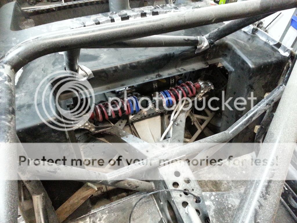
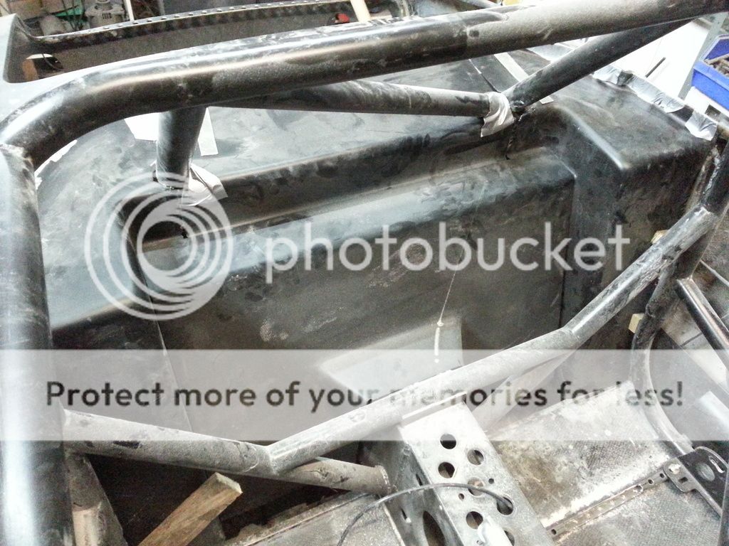
Glued in rear panels this afternoon. Access to rear suspension is pretty good. Panels are, of course, made from 2 layers of carbon fibre :) The centre panel will be removable.


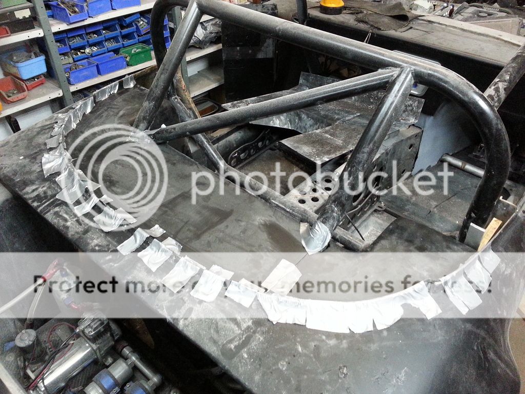
Started to think about the front firewall/bulkhead. I had planned to place it on the dash side of the crossbar, but this doesn't leave enough room for the battery so it will have to go the exhaust side. I will just have to add additional heat shielding. It will be made from, as the rear panels, 2 layers of carbon fibre.


Tyres...bloody tyres, still trying to work out the best combination. I thought I had finally cracked it after years of searching with the Michelin TB5s. However, the size options for 15" rims are restricted and the smallest size for the front is a little high on the aspect ratio (50) than I would like, the 225mm width option is only 5mm smaller in diameter than the 285 rears I planned to use.


Pirelli do a P7 Corsa Classic in 305/35 and 235/45 with diameters within 1mm so similar difference but they come in three softness grades. What I can't find out are the Mu values so I can compare 'stickiness'. One of my main tasks at the NEC in January is to discuss this problem with both Pirelli and Michelin to see if I can resolve my (potentially expensive) dilemma as the tyre size dictates wheel width as this has to match the footprint width in order to wring out the maximum grip (bloody idiot tyre stretchers please note!)

 
Fitting rear wing struts:


Gluing in home made carbon angle for fittings for centre console:


Plenty of consumables for next year :) :

 
Had a bit of a giggle this morning. I was on Pistonheads yesterday looking for my old Elan build thread that I thought I had started a few years ago. I couldn't work out how to go back further than 90 days so asked the question. Quite a few replies and the problem (me not knowing how to use the forum history function) was solved. However, a lot of people posted suggestions, including this one:

"I've done it to 6000 days (17 years, albeit rather pointless) and he hasn't started any such thread so he's full of *#*#*#*#."

I replied "Sure looks that way
1f642.png
Now that I know how to look I have done the same and, as you say, there is no such thread. I guess that's old age memory for you. I have been running threads on couple of other forums and, having been a member on here for a few years, I assumed I had started one here."

I then posted "If anyone would be remotely interested I could start a thread, if only to show that I am not completely full of male cow excretion
1f642.png


1967 Lotus Elan
520bhp on regular pump fuel
Road legal"

I await a response
1f642.png
 
:) What are drl foglight surrounds?

View media item 4680
If you look at the fog lights in the pic, I have bought replacement surrounds which have an integrated DRL strip.

They look a bit like this:
http://www.carlsson.de/b2b/index.php?func=browse&mfid=1&tid=40&vid=383&cat=83

http://www.carlsson.de/imgpopup.php?f=62360600

But mine are just the surround, not the lights.

I had a look and I'm not sure if I might have to heat the plastic of the slots in the bumper so I can get the existing one out.

I wouldnt worry about PH, they have their heads massively up their own backsides on there.
 
A little progress. Glued in dash unit and trimmed top edge so the top fits properly. Once glue has set I will secure firewall and then glue dash top on for good.


Glued the top section of the firewall in this afternoon. Using structural expoxy adhesive so this will, in a small way, add to the tortional stiffness, every little helps :)

The wooden resin mixing sticks were a perfect length with just enough springiness.

This will get very hot so will be faced with Zircotec's Zircoflex III flexible heat shield material. Bloody expensive but bloody good.

 
Just come up against one of those little challenges that you expect on a unique build. Started to sort out the centre console whilst the glue cures on the firewall. Cut the hole for the handbrake which worked out fine. However, a problem I had in the back of my hand reared its ugly head. I can't remove the console over the lever as it can't be moved forward in order to slide the lever through the hole. The console can only be fitted and removed vertically due to dash and roll cage.


Initial thought was to remake lever, using the part that connects to the master cyliinder and frame, with a removable aluminium handle (screwed on).

However, a friend suggested two carbon tubes, one sliding inside the other. Problem would be securing one of the tubes to the remaining part of the lever. So, aluminium tube welded to lever then carbon tube sliding over this. Sounds like a plan and ligher than my original design :)
 
Re the above handrake issue, I just need to get it welded (my TIG skills are still minimal) and tidied up.

A key mantra of mine is that any mods should make the new/replacement part lighter than the original, whenever possible. In this case a 115g, or 44%, reduction is pretty good. Once the carbon in sanded and painted you will not realise what it is :)


A small grub screw will secure handle to base.


I made a carbon roof in a day but have spent more time trying to decide on how to release the handbrake
icon_smile.gif


The Rally Design unit is designed to be used in an exposed location, not covered by a console. The release is a simple latch that is lifted by hand. However it is inaccessible under the console.


So I need to work out some kind of opperating mechanism that is accessible and neat. Simplest would be a rod and knob fitted vertically to one end of the latch, either to pull or push the latch. I also thought of a bowden cable strapped to the handle but this would have to be detatchable so the handle could be removed.

Any ideas? Are there any such items already out there that I could adapt?
 
Been thinking, why not use a 12v actuator? However, I can only find, at the moment, 24v units with the small throw (10mm) I require. The question is, as I don't require much force, can I run these on 12v?


STOP THE PRESS!

Just found a small 12v solenoid :)
 
Handbrake finished, apart from a litle more polishing. As soon as the 12v solenoid arrives from China I will find out if my lift mechanism will work.

The button was in my collection of switches and lamps left over from my steering wheel build :)


Drift? What's drift? I'm talking about real racing, not fannying about wearing tyres out.

He probably already has one :)
 
Drift? What's drift? I'm talking about real racing, not fannying about wearing tyres out.

Steve may I suggest that you avail yourself of a ride in a drift car with a good driver then you hopefully will appreciate the high level of car control skills involved.;)
I have had that experience and had to suck on a lemon to wipe the smile away.


PS I am not the least bit interested in burnouts and donuts unless they are covered with sugar :lol:
 
Oh, I don't dispute the skill required to drive these cars fast, or the technology involved, it just isn't racing as far as I am concerned. Entertainment for the masses that require constant visual stimulants, certainly, but not for the pure racer who simply wants to go as fast as possible which is what racing is all about. Take away the smoke and what have you got? The childhood game of follow my leader :)
 
They get extra brownie points for overtaking as well as for angle,smoke and proximity as explained to me by a drifter but know it's not everybody's "cup of tea":)
 
Trying to make one roll of Earl's 1/2" aluminium fuel pipe do both feed and return was, in good ol' hindsight, a mistake as it has caused me a few issues with a messy, and heavy, bodge the result.

However, we are getting there. One problem I had was that there isn't a bulkhead fitting with a female end, so I have had to make one. The right hand one is the original male/male bulkhead fitting.


It works, but isn't exactly pretty or light. The large red cylinder is an additional filter after the pumps, just in case.

 
Last edited:
Not a lot going on at the moment.

I couldn't find any male/female bulkhead fittings so they had to be made. Final setup looks a bit messy but all the connectors are necessary and kept to a minimum. However, a little bit of paint will tidy them up :)


Existing 11 litre fuel tank had fuel filler tube added plus a sender unit. An additional 22 litre tank was made to allow journeys of more than 1/4 mile. This will be fitted with quick release connectors. Filler cap had a filler tube attached, hopefully this will line up with the tank tube :)


Looking at alternative boot and bonnet fasteners to Dzus. Found these on AliExpress at around 8 pounds each. Rather large at 2.5 inches in diameter (left hand one) so I stuck one on the lathe and gave it a thorough thrashing.


Reduced weight by 25% but still looks a tad large. So a little more surfing resulted in these little beautires. They range from 1.5 to 0.875 inch diameter and I have ordered four of the 1.25mm diameter variety.

http://www.quik-latch.com/quik-latch-mini-latch.html

Nearly three times the price but smaller and lighter. My daughter is in Virginia at the moment so I am having them sent to her in order to save around $30 in shipping.
 
The roll cage, coupled with new seat, has resulted in my seating position being moved forward around 100mm. This has made operating the pedals very difficult so I am having a rethink. The pedals are as far forward as they can go. I can't move the bulkhead forward as there is only 25mm clearance between it and the tyre. The pedals are 140mm in front of the bulkhead. research has come up with this option from OBP. The roll cage stops me from fitting a top mounted box. The floor mounted OBP box with rearward facing master cylinders allows me to recess the unit into the floor if necessary.

Existing setup. Roll cage cross bar interferes with feet and no room to hang pedals from the top.


Tyre clearance precludes moving bulkhead.


Existing pedals are around 150mm from bulkhead.


This box should, hopefully, make life easier, not perfect, but easier.


On a brighter note, auxillary fuel tank has arrived and fits perfectly. As soon as the quick release connector turns up I can complete the boot area fuel system plumbing.

 
OK, I have a plan (but it may change
1f642.png
)

Use this pedal box and fit reserviors directly to master cylinders. However, cylinders sit at an angle so I will have to remove existing bolt tabs and make new ones.


Available threaded reserviors are too tall so they will be attacked with my lathe until they are the right height. Bought this reservoir on eBay to experiment with.


I may have to recess the box into the floor but won't know that until it arrives and I can do some real life testing.
 
The larger of the two 12v solenoids/actuators arrived from China today so I was able to perform a handbrake release mechanism proof of concept test. I used a Duracell 9v battery as the power source. The unit will be fitted inside the handbrake housing and don't worry, I will use black tape.

The piston will push up the aluminium bar that is visible just above it, releasing the handbrake.

I will use the smaller unit in the final build, so if anyone has a use for this one let me know.

 
Had a play this afternoon with how to fit the boot. I think I have worked out what I am going to do. A pair of mini-latches at the rear with the boot sliding into some tubes at the front edge. Knocked up the threaded aluminium bars on the lathe and they will be cleaned up prior to final fitting. A couple of the lightening holes I drilled are serving more than one purpose. Colin Chapman would be proud of me :)


Fitting boot lid. The carbon fibre boot lid was made (not by me) using the original lid as the pattern, so is slightly bigger. Even so, the fit is crap, or perhaps I should say within normal Lotus tolerances. Gap was uneven and big so I decided to attempt to remedy this.

First, I had to make the boot lid fit as best I could. I decided to secure the front face using 4 carbon (obviously) dowels glued to the boot lid that slide into 4 carbon tubes fitted to the body. This worked out pretty well, even if I do say so myself. Next task was to work out how to fill the gap. My method, if it works, was to fill the gap completely, using (yes, you guessed) carbon fibre filler then to trim to the desired gap.

In order to prevent filler falling into the boot a barrier of Corex was hot glued to the underside of the boot lid surround. The boot lid edge was covered in masking tape in order to prevent the filler sticking to it (time will tell if this works). Filler was then used to fill the gap between lead and body. The bricks were used to align the lid with the body. Stiffening will be added to the lid to keep it to this shape at a later date.


The experimental master cylinder reservior arrived today. Needed to check that the aluminium used is suitable for welding before buying another two. Cut it down to size and thinned the walls and cap. Original weight 227gms, now weighs 97gms, 31 of which are in the steel fitting so I will make some aluminium ones :) It welded fine so I will order two more. The shortened height will help in fitting them under my legs in the floor. Also saves around 400gms.


After an hour and a half of sanding and trimming, the boot finally came out! Next job is to tidy the filler up and infill some voids. Then I have to decide on a gap width and set about sanding.


New pedal box arrived yesterday. Very well built but heavier than claimed. Website says 2.8kg but it is a little over 3.4Kg

However, there is a lot of scope for lightening so I will attack it over the next couple of weeks.

Dry fitting box confirmed that it has to be recessed into the floor. I will also see if I can move the bulkhead/wheel well forward 20-30mm.


Modified master cylinder reservoir (shortened and lightened)) fits but was a little high so I reduced length of fitting. Every little helps. I will be replacing them with aluminium ones as soon as my 5/8" die arrives
icon_smile.gif


However, there is no guarantee that the reserviors will remain where they are. It depends on how they interact/interfere with my feet.
 
Things don't always go to plan. I was modifying the next two master cylinder reservoirs yesterday. First one went fine and so did the second one until I relaised that I had made it slightly too tall. So back on to the lathe it went. I had to hold it internally in order not to risk damage to the thread but this hadn't been a problem, I just had to be circumspect and gentle with my tool feed. This time, however, I must have got just a little bit too ambitious and twang! it flew out of the jaws and ended up like this. Oh, well, not the end of the world :)

 
Doesn't take much for something to pick up and throw itself out of the chuck when working with such thin walled parts. That's why it's important to wear safety glasses and good fitting underwear!
 
Sometimes familiarity breeds contempt OR complacency especially when one has done things 100's of times.
I only had an accident with any power tool, a grinder long after I stopped building.
Take care Steve as I'm sure all who have followed your epic build want you succeed and set the time for the fastest Elan on the planet.
 
Thanks for your concern. My Dad was an engineer and instilled a healthly respect for machines into me. I wear a full face shield when cutting or grinding. When grinding I also wear safety glasses under the shield as sparks manage to get under even this!
 
Design change with regard to fluid reservoirs. They will be in the way on the floor, wherver I fit them so a rethink was required. After a lot of thought (wanted to keep them out of the engine bay) I decided to place them behind the dash on an opening bracket. Playing with SketchUp I have come up with this:


New pedal box arrived, but, at 3.4Kg, it was 600gms heavier than advertised :-(. After a lot of milling and drilling it is now 2.9Kg:


The master cylinders were facing the wrong way so new holes had to be drilled.


As gettng to the bolts would be a pain when installed I welded them in. I also welded on nuts over all the fixing holes, thereby making fitting and removal a breeze (relatively).

I have had to lower the box into the floor in order to get enough pedal clearance. This has worked out Ok.


My hydraulic handbrake is designed for cars with no central console as you have to lift a small bar to release it. After some thought I have built and electric mechanism that lifts the bar when a button fitted to the handbrake it pressed. Like normal cars but electric rather than mechanical. The soleniod is tiny (top one) - 16mm x 14mm x 20mm and is just powerful enough.


Proof of concept was done using the larger soleniod:


The smaller one just fitted between the case and the master cylinder rod.
 
Bloody expensive, but I like these latches. A pair used to secure central console. Had to make a couple of brackets to fit the latch pins to. I also reduced the diameter of the latches to 27mm. Why? Because I can
1f642.png


The bolt securing the rear latch tube to the chassis is aluminium but the bolt holding the front bracket needed to be stronger so is titanium.


If or when the Elan gets "finished"you will be lost for something to do with all the spare time you will have;)

Am still envious of all your skills you have shown throughout the build |B

I would have thought you would have described your face as "ruggedly handsome" :)
 
As you well know, a race car is never finished. I already have plans :)

They are all 20 feet skills :)
 

Similar threads


Please watch this on my YouTube channel & Subscribe.


Back
Top